


Version: 1.0, September 19, 2002
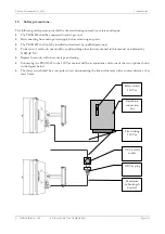
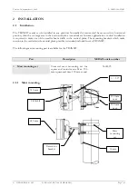
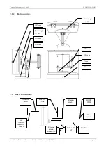
2 – INSTALLATION
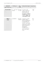
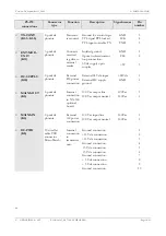
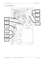
2.4.1 PS-270
connections.
PS-270
connections
Connector
type
Function
Description
Signal names
Pin
number
•
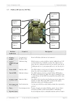
Reflex-130 INT
(K16)
5-p mkds
phoenix
External
connection
Reflex-130
120 kHz antenna con.
120 kHz antenna con.
LED cont. high pos. ID
Ground
LED cont. high neg. ID
HF+
HF-
UL
GND
NA
1
2
3
4
5
•
Reader disable
(K7-1..K7-4)
5-p mkds
phoenix
Controls
the flow of
data to the
controller.
Spare
Spare
Reader disable
+5 Vdc connection
R-dis
5V
1
2
3
4
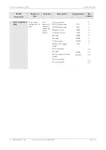
•
B-W-O-OUT
(K7-5)
5-p mkds
phoenix
Code
emulation.
Output for Omron,
Wiegand and Barcode.
GND 5
•
B-W-O-OUT
(K4-1..K4-3)
5-p mkds
phoenix
Code
emulation.
Output for Omron,
Wiegand and Barcode
Ground
O-1
O-2
O-3
1
2
3
•
Door contact
(K4-4..K4-5)
5-p mkds
phoenix
Door
contact
Door contact
Ground
Door
GND
4
5
•
RELAY-CONT
(K6)
3-p mkds
phoenix
Floating
relay
contacts
Center contact
Normally closed contact
Normally open contact
COM
NC
NO
1
2
3
•
DATA-CNTL
(K14)
6 wire flat cable
PCB connector
Micro Match
Internal
connection
to
transceiver
unit
Ground connection
Spare
TTL received tag data
Received signal strength
TTL signal PLL locked
TTL signal enable TX
GND
Det-data-out
U-AGC
Locked
TX-enable
1
2
3
4
5
6
•
120 KHZ-MOD
(K1-1..K1-2)
2-p mkds
phoenix
120 kHz
input from
external
NEDAP
inductive
reader
120 kHz connection
120 kHz ground con.
HF+
HF-
1
2
s
© NEDAP IDEAS – AVI
P.O. Box 103, NL-7140 AC GROENLO
Page 15-41


