background image

Version: 1.0, September 19, 2002 

1 – Introduction.


© Nederlandsche Apparatenfabriek N.V.   (IDEAS- AVI) 

Parallelweg 2E 

P.O. Box 103 

NL - 7140 AC Groenlo 


FCC ID : CGD TRANSIT 

 
The device complies with part 15 
of the FCC rules. Operation is 
subject to the following conditions: 

operation. 

(1) This device may not cause 
harmful interference, and (2) this 
device must accept any interference 
that may cause undesired 


The products described in this document may be subject to modifications without corresponding updating of the document. 
© Copyright 2002 Nederlandsche Apparatenfabriek N.V.   (IDEAS- AVI)


©  NEDAP IDEAS – AVI  

P.O. Box 103, NL-7140 AC GROENLO

Page 2-41 


Summary of Contents for TRANSIT-USA

Page 1: ...to its accuracy or completeness its publication conveys no license under any patent or other right nor does the publisher assume liability for any consequence of its use specifications and availabilit...

Page 2: ...tion is subject to the following conditions operation 1 This device may not cause harmful interference and 2 this device must accept any interference that may cause undesired The products described in...

Page 3: ...1 Connections to inductive readers 25 3 2 Connections via the special code emulation outputs 25 3 3 Removing the optional communication boards 25 3 4 RS 232 RS 232 III Art No 7806434 26 3 5 RS 422 CM...

Page 4: ...T system has a wide range of tags for various applications Lithium batteries energize the tag circuit which gives lifetimes up to 10 years Heavy duty tag is developed for vehicle applications The Wind...

Page 5: ...TRANSIT 120 Vac USA Extended PS 270 Extended version of TRANSIT for access control systems and parking systems t b d Opened Cover Transceiver unit Location optional com Board Power supply unit PS 270...

Page 6: ...modify or add anything other than mentioned in this manual or indicated by NEDAP NV Replace fuses only with the same type and rating Connecting the TRANSIT to the 120 Vac mains shall be in accordance...

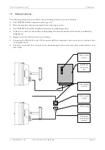
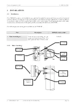
Page 7: ...width in the vertical plane The mounting brackets which make rotation in the vertical and horizontal plane possible is standard included in every TRANSIT The following mast mounting part is available...

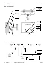
Page 8: ...mm Turn angle 45 245 mm 9 mm Turn angle 30 310 mm 100 mm 100 mm 2 2 Basic connections RELAY CONT MAINS Reflex 130 INT External antenna Reflex 130 Host system HOST COM 120KHZ MOD Any NEDAP inductive re...

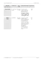
Page 9: ...NC NO Reflex 130 INT 4 0 25 mm2 shielded Maximum 15 meter Connection to the external inductive antenna Reflex 130 HF HF UL GND NA HOST COM B W O OUT 4 0 25 mm2 shielded Maximum 50 meter Detected tag...

Page 10: ...e Reader disable input Using an external 5 Vdc voltage can damage the unit Rdis 5V 120KHZ MOD Coax RG58U Maximum 100 meter Connects any external NEDAP inductive reader to the TRANSIT The TRANSIT shall...

Page 11: ...5 S 5 SUBBAND 6 S 5 SW1 1 SW1 0 Frequency kHz S 1 S 2 S 3 S 4 Frequency kHz S 1 S 2 S 3 S 4 2 438 400 1 1 1 1 2 448 000 1 1 1 1 2 439 000 0 1 1 1 2 448 600 0 1 1 1 2 439 600 1 0 1 1 2 449 200 1 0 1 1...

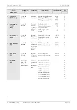
Page 12: ...ver unit indications PLL LOCKED D 7 Indications Transceiver unit Indication type Description Indication number PLL LOCKED Dual color LED Red indicates PLL is unlocked Green indicates PLL is locked D 7...

Page 13: ...ustment number FREQ FINE Trim cap Factory setting Fine tuning reference frequency for synthesizer C 105 TX PWR Trim pot Customer setting Reduction transmitter power by maximum 20 dB Maximum EIRP 18 dB...

Page 14: ...4 Door contact K4 4 K4 5 120 KHZ MOD K1 1 K1 2 MAINS OUT K5 TX CONT K1 3 K1 5 DC SUPPLY K10 EXT MOD UNIT K11 Reflex 130 INT K16 B W O OUT GND K7 5 DC PWR K8 MAINS IN K3 PLACE THIS CONNECTION WHEN DOOR...

Page 15: ...1 K4 3 5 p mkds phoenix Code emulation Output for Omron Wiegand and Barcode Ground O 1 O 2 O 3 1 2 3 Door contact K4 4 K4 5 5 p mkds phoenix Door contact Door contact Ground Door GND 4 5 RELAY CONT K6...

Page 16: ...power connection External 24 Vdc input External DC supply ground 24Vdc GND 1 2 MAINS OUT K5 2 p mkds phoenix Internal connection to NX 500 optional board 120 Vac output line 120 Vac output neutral 12...

Page 17: ...ction to optional communi cation board Not connected TTL TX data com TTL RX data com Ready to send Cleared to send Ground Ground 5 Vdc output RS 485 I O toggle signal Not connected Ground 24 Vdc outpu...

Page 18: ...LLATION 2 4 2 PS 270 U Link DIP switch settings 2 4 2 1 U links Range beep on off K 15 Inductive Mod select K 13 DATA DATA modulator K 12 DATA DATA controller K 9 DIP SWITCH SW 1 NEDAP IDEAS AVI P O B...

Page 19: ...data from uW receiver and inductive receiver to modulator default Inverts inductive modulator data 2 Inverts TTL data from uW receiver and inductive receiver to modulator K 12 Inductive Mod select 1 S...

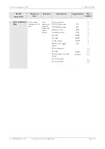
Page 20: ...2 4 3 PS 270 indications RX LEVEL D 28 D 30 PLL LOCKED D 2 DOOR CLOSED D 15 DC RAW D 17 5 Vdc PRESENT D 22 15 Vdc PRESENT D 23 15 Vdc PRESENT D 24 RANGE BUZZER X 1 STS ID D 14 NA UL D 6 NEDAP IDEAS A...

Page 21: ...tes that this voltage is present D 24 NA Dual color LED red LED indicates that the TRANSIT is standby and the door is locked D 6 UL Dual color LED green LED indicates that a tag is detected shall stay...

Page 22: ...FUSE 0 3A SB 24 Vdc FUSE 1A SB 24 Vdc FUSE 1A SB Reflex 130 INT K2 11 K2 16 D1 PROG STATUS D2 DETECTION STATUS D3 PORTER CONTACT D4 DOOR CONTACT D5 RELAY ACTIVATED OPT COM INT K4 DOOR CONTACT K2 9 K2...

Page 23: ...ply intended for lock control 3 4 24VDC GND RELAY CONT K2 5 K2 7 3 0 75 mm2 25Vdc 2 A 120Vac 1A Relay contacts normally open center contact and normally closed 5 6 7 NC COM NO MANUAL RELEASE K2 8 K2 9...

Page 24: ...12 13 14 TX RX RTS CTS GND GND XV5P I O GND XV24P 2 5 2 Indications NX 500 Indications Indication type Description Indication number PROG STATUS LED red 1 sec on 1 sec off Program is operational 1 sh...

Page 25: ...it allows for the selection between voltage or current coupled receivers Contact NEDAP when in doubt which kind of external inductive receiver you want to connect to the TRANSIT system Remember that w...

Page 26: ...le connector 15 8 mm Connec tion to Power supply unit See par 3 1 3 2 See par 3 1 3 2 See par 3 1 3 2 RS232 3 pin CON K 3 3 pin WECO PCB RS 232 connection Transmit output Ground Receive input Tx GND R...

Page 27: ...a 120 resistor The TX and TX lines have to be terminated at the host side Connection to host RX TX host RX TX host TX RX host TX RX host Internal interface CM 422 Connector type Function Description...

Page 28: ...le Connected over the network 3 6 1 2 Red LED If the red LED is on or blinking the green LED will give a diagnostics code There is a fatal error and the UTS is not working Red LED stable on green LED...

Page 29: ...This LED indicates that power is available This LED should always be on as soon as power is turned on Status LED Indication Green This LED indicates the status of the Profibus DP Interface Module and...

Page 30: ...problem for the detection range Heavy rain shall be no problem as long as there is no closed water film on the TRANSIT front cover or on the label To reduce the influence of unwanted reflections circ...

Page 31: ...oned parameters before a specification on the maximum speed is defined This speed can ONLY be obtained with firmware in the 54 bit detection mode see firmware user manuals 4 4 Using more systems at th...

Page 32: ...eiver unit This AGC voltage represents the received signal strength of a transponder in front of the TRANSIT When the orientation is fixed and no changes are present in the propagation path when the t...

Page 33: ...Locally the squelch level can be set by means of potentiometer P 2 when the U links K 7 and K 6 are set for position 2 Remotely the squelch level can be set by means of software commands when the U li...

Page 34: ...le is 0 degrees the reader looks parallel to the ground When D angle is 90 degrees the reader is looking straight down A angle Angle over which the reader is rotated in the horizontal plane L height M...

Page 35: ...trong reduction in the detection area 4 6 4 Example 3 Rpow 5 4 3 2 1 0 1 2 3 4 5 0 1 2 3 4 5 6 7 8 9 10 80 80 90 90 90 100 100 100 100 110 110 110 110 110 120 120 120 120 120 120 120 130 130 130 130 1...

Page 36: ...ngle to 15 the range is again improved 4 6 6 Example 5 0 Rpow 5 4 3 2 1 0 1 2 3 4 5 0 1 2 3 4 5 6 7 8 9 10 60 70 80 80 90 90 90 90 100 100 100 100 100 100 110 110 110 110 110 110 120 120 120 120 120 1...

Page 37: ...ion is 0 2 The labels is at a height of 1 meter and is looking straight up 4 6 8 Example 7 Rpow 5 4 3 2 1 0 1 2 3 4 5 0 1 2 3 4 5 6 7 8 9 10 95 95 95 100 100 100 105 105 105 105 110 110 110 110 110 11...

Page 38: ...5 125 125 130 130 130 135 135 135 135 135 140 140 140 145 145 150 150 170 Received power 105 dBm minimum Parameter Value R height 3 D angle 15 A angle 30 L height 1 25 L angle 60 This example is typic...

Page 39: ...GATE MASTER firmware needed Internal relay controls gate Inductive antenna Transponder Card 120 Vac or 24 Vdc Internal relay controls gate Communication to Host WIN GATE TRANSIT Extended Max 1000 tag...

Page 40: ...0 60 Hz 24 Vdc 10 500 mA DC supply shall be capable of delivering a 1 A inrush current Power consumption 30 VA TRANSIT Extended 18 VA TRANSIT Frequency range 2438 4 MHz 2457 0 MHz Selected by DIP swit...

Page 41: ...can also be read and programmed inductively Heavy duty tag R O 9875689 This tag is a heavy duty tag that can be mounted at the outside of many vehicles and is capable of exposure to harsh environmenta...

Page 42: ...her right nor does the publisher assume liability for any consequence of its use specifications and availability of goods mentioned in it are subject to change without notice it is not to be reproduce...

Page 43: ...ON 5 4 1 DC2 DC4 PROTOCOL 5 4 1 1 EVENT MESSAGES 5 4 1 2 COMMAND MESSAGES 7 5 FIRMWARE UPGRADING 12 6 FIRMWARE REVISION HISTORY 12 A HARDWARE 13 B ASCII TABLE 14 C DC2 DC4 PROTOCOL 15 C 1 DATA FORMAT...

Page 44: ...le The booster unit is a special window tag which is able to hold a NEDAP inductive identification card This card is read by the booster The combi booster combines the features of the window tag with...

Page 45: ...icles at high speed it is recommended to keep DIP switch 8 in ON position Note2 Set DIP switch 7 to OFF when no combi booster or EF coded transponders a re to be identified This increases the detectio...

Page 46: ...hey occur are stored locally in the reader in the event buffer Once communication is idle the reader will try to transmit the event message A maximum of 3 event messages can be stored When the event b...

Page 47: ...D 2 ID 1 ID 2 End of detection Figure 2 Timing diagram end of detection event U event Combi booster identified Description When a combi booster is identified this event message reports both identifica...

Page 48: ...1 2 COMMAND MESSAGES The following command messages may be sent to the reader Protocol dependent characters are not shown here 20 Check communication Description Command message can be used to check t...

Page 49: ...reader This is the same as turning the power off and back on again and will therefore be followed by an O event reader restart All EEPROM settings are unaffected by this command Syntax 01010163 W or...

Page 50: ...0101010255 Reply 0101010255AABBCCDD Where AA Relay hold time in the range from 1 to 255 tenths of seconds Use decimal to ASCII conversion table BB Unused parameter reserved for alarm time CC Unused p...

Page 51: ...y 0101010266m Where m 0 disabled default 1 enabled Notes See command message 0265 0267 Set end of detection mode Description The end of detection event is a detection event with identification number...

Page 52: ...rs are identified 1 manual Relay is only activated and de activated with command messages 0272 0274 and 0276 Notes See command message 0270 0272 Activate relay Description Activate unlock relay The re...

Page 53: ...wnloader searches for the bootloader 5 If the TRANS IT is properly connected and PIC downloader is setup correctly the firmware is downloaded The window should look like shown in Figure 5 6 Once the d...

Page 54: ...ARE The P61 firmware is developed for the TRANS IT PS 270 microwave reader Below an overview of the hardware components is shown For more details about the connections and electrical specifications re...

Page 55: ...43 2B 75 4B K 107 6B k 12 C FF 44 2C 76 4C L 108 6C l 13 D CR 45 2D 77 4D M 109 6D m 14 E SO 46 2E 78 4E N 110 6E n 15 F SI 47 2F 79 4F O 111 6F o 16 10 DLE 48 30 0 80 50 P 112 70 p 17 11 DC1 49 31 1...

Page 56: ...he data message When there is no ACK response within 4 seconds the communication is aborted Both reader and host can startup the communication by sending a DC2 When the reader and the host startup the...

Page 57: ...wing the procedure below 1 Sum all character values in the message STX ETX and the checksum itself not included 2 This sum must be shortened into 1 byte 3 Split this byte up into two bytes 4 Finally a...

Page 58: ...NAK Timeout 4 sec CommTries 3 DC4 Timeout 2 sec Goto BEGIN YES NO NO YES NO NO NO YES YES YES YES NO Transmit Receive Send Msg YES NO DC2 YES NO DC4 Timeout 0 STX YES NO Timeout 4 sec NO YES Receive...

Page 59: ...75 4 107 6 139 8 171 203 235 12 0 44 2 76 4 108 6 140 8 172 204 236 13 0 45 2 77 4 109 6 141 8 173 205 237 14 0 46 2 78 4 110 6 142 8 174 206 238 15 0 47 2 79 4 111 6 143 8 175 207 239 16 1 0 48 3 0...

Reviews: