18
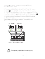
Connecting the wires to the PowerRouter terminal blocks.
Use 2.5 mm² wires minimal.
1. Turn OFF the main breaker in the main utility breaker box.
2. Connect the AC Grid/Utility ground wire to the AC Grid/Utility terminal
labeled
3. Connect the AC Grid/Utility L wire to the AC Grid/Utility terminal labeled L
4. Connect the AC Grid/Utility N wire to the AC Grid/Utility terminal labeled N
5. Connect the AC Line Out ground wire to the AC Line Out terminal labeled
6. Connect the AC Line Out L wire to the AC Line Out terminal labeled L
7. Connect the AC Line Out N wire to the AC Line Out terminal labeled N
8. Tighten strain reliefs.
Verify that all connections are correctly wired and properly torqued.
(min. 1.2 Nm, max. 1.5 Nm)
Figure 11 AC Connection terminals
Contacts need to be free of any mechanical strain.
AC Grid/Utility
AC Line Out
N
N
L
L
AC Grid/Utility AC Line Out
!
caution
Summary of Contents for PowerRouter PR50S
Page 1: ...PowerRouter installation and operatingmanual Solar 5kW 3 7kW 3kW English...
Page 2: ......
Page 56: ...56 Notes...
Page 57: ...57...
Page 58: ...58...
Page 59: ...59...
Page 60: ...60...
Page 61: ...61...
Page 62: ...62...
Page 63: ...63 the PowerRouter you re in charge E welcome PowerRouter com I www PowerRouter com...
Page 64: ...64 your installer Manual part no 5277337 A 01 the PowerRouter you re in charge...


