background image

9

© by NECTA VENDING SOLUTIONS SpA

0404 211 - 02

Chapter 2

INSTALLATION

The machine installation and the following mainte-
nance operations should be carried out by qualified
personnel only, who are trained in the correct use of
the machine and are aware of the specific risks of such
operations.

The machine is not suitable for outdoor installation, it
must be installed in a dry room where the temperature
remains between 5°C and 32°C.

It cannot be positioned where water jets are used for
cleaning (e.g. in large kitchens, etc.).

The machine should be positioned with a maximum
inclination of 2°.

The relative humidity must not exceed 65%.

UNPACKING THE VENDING MACHINE

After removing the packing, ensure that the machine is
intact.
If the vending machine is found to be damaged, immedi-
ately inform the carrier and do not use the machine.

No packing elements (i.e. plastic bags, polystyrene
foam, nails, etc.) should be left within the reach of
children, as they are potentially dangerous.

Packing materials must be disposed of in authorised
containers and the recyclable ones must be recovered by
qualified companies.

If the vending machine had been laid down during
transport, allow at least one hour before connecting it
to the mains.

INSTALLING THE PAYMENT SYSTEM

The machine is sold without payment system, there-
fore the installer of such a system has sole responsi-
bility for any damage to the machine or to things and
persons caused by incorrect installation.

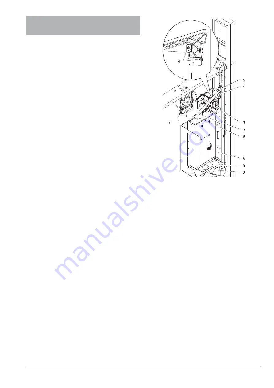
Install the coin mechanism paying attention, according to
the type used, to:

- choose the most suitable securing holes;

- loosen the fastening screw and adjust the coin slot

chute according to the coin mechanism opening;

- loosen the fastening screws and adjust the selector

opening lever;

- to aid installation the coin mechanism support plate

can be lifted and rotated.

Fig. 12

1 - Coin chute fastening screw
2 - Coin chute
3 - Selector opening cam
4 - Selector lever fastening screw
5 - Coin mechanism securing holes
6 - Coin mechanism compartment door
7 - Coin mechanism
8 - Coin slot chute
9 - Coin return chute

Summary of Contents for Sfera

Page 1: ...INSTALLATION USE AND MAINTENANCE MANUAL UK English Sfera DOC NO H 211U 02 EDITION 2 2004 04...

Page 2: ......

Page 3: ...a de identificaci n resulta conforme a las disposiciones legislativas de las directivas 89 392 89 336 73 23 CEE y modificaciones y integraciones sucesivas Declara que o distribuidor descrita na chapa...

Page 4: ......

Page 5: ...PAGE 10 MAIN SWITCH PAGE 11 DISPENSING COMPARTMENT MANUAL RELEASE PAGE 11 OPERATING MODES PAGE 12 USER INTERFACE PAGE 12 DIRECT SELECTIONS PAGE 12 NORMAL OPERATING MODE PAGE 12 FILLER MENU PAGE 12 ST...

Page 6: ...ng plate attached inside the cabinet on the right side This plate see figure below is the only one acknowledged by the manufacturer as the identification of the apparatus and carries all the data whic...

Page 7: ...rfunc tioning of the cooling unit The machine should be positioned with a maximum incli nation of 2 If necessary provide proper levelling by way of the adjust able feet included WARNING FOR INSTALLATI...

Page 8: ...tructions which must be strictly observed to ensure the machine safety Installation and the following testing operations must be carried out exclusively by personnel who have a specific knowledge of t...

Page 9: ...ional sets of use keys silver may be requested indicating the combination stamped on the keys Generally only the use key silver is used while the combination change keys gold can be kept as spares Fig...

Page 10: ...ments two spirals right hand and left hand in each product holder for large size products or into 75 mm compart ments one right hand spiral in each product holder for small size products When dispensi...

Page 11: ...dam age caused by non compliance with the above men tioned precautions and with current regulations At least every six months it is necessary to clean the ventilation grilles of the cooling system us...

Page 12: ...nserting the product in the spiral More fragile products must be placed on the lower trays to prevent damage when they drop START UP Each time the machine is started the number of trays connected to t...

Page 13: ...h of children as they are potentially dangerous Packing materials must be disposed of in authorised containers and the recyclable ones must be recovered by qualified companies If the vending machine h...

Page 14: ...bles type HO5 RN F or HO5 V V F or H07 RN F with a 3x1 1 5 mm2 section CONTROLS AND INFORMATION The user controls and information are located on the outside of the sliding compartment see Fig 13 The c...

Page 15: ...t When sliding sideway all the shutters on the cold air distribution duct lining up the duct holes with the ones on the shutters shutters in the open position a uniform temperature is obtained in the...

Page 16: ...rd feature or asoptionalaccordingtothemodel witha5 buttonkeypad to which allocate a group of selection After enabling the direct selection function it will be possible to allocate a group of selection...

Page 17: ...ICES FOR SINGLE SELECTIONS This function is used to change the sales price for each selection according to the time band Key is used to access directly the price selection settings if the function is...

Page 18: ...he next button is presented Temperature The value of temperature detected by the probe is dis played In the event of disconnection the value 11 0 is displayed In the event of a short circuit the value...

Page 19: ...sh Prices Coin mechanisms Decimal point Bonus Spirals select Spiral parameters Photocells Disp comp lock Cold parameters Display Language User messages Promotional message Personalised strings Display...

Page 20: ...ly 1 second Scrolling through all failed motors is automatic Note By restarting the machine any blocked motors are de tected as not present Dispensing compartment lock When the function unlock compart...

Page 21: ...ending Setting the operating mode for multiple or single dispens ing With multiple dispensing the change is not automati cally returned after a successful selection however the credit is available for...

Page 22: ...possible to define which among the coins recognised by the validator are to be accepted when the change tubes are full Check the coin mechanism configuration for the correct coin to value matching Ret...

Page 23: ...e installed in the machine PRODUCT CODE This function is used to assign a 4 digit identification code to each spiral for processing the statistics DIRECT SELECTIONS The vending machine can be fitted a...

Page 24: ...le ones to be used for the messages on the display DISPLAYING MESSAGES FOR THE USER It is possible to choose the kind of information to be indicated on the display during normal operation The followin...

Page 25: ...etobeswitched on when the machine is out of service or during the Energy saving time band STATISTICS Data on the machine operations is stored in both general countersandrelativecounters whichcanberese...

Page 26: ...he event there was no money available for return Aud 7 Total sales Total value of sales Aud 8 Exact change Value of sales in the no change condition Aud 9 Mixed dispensing Totalvalueofdispensingpaiddi...

Page 27: ...ocking the dispensing compartment opening usethe and buttonstolockandunlockthe compartment opening Direct keypad If fitted on the machine the 5 buttons are checked sequentially Press the button reques...

Page 28: ...send via GSM modem a signal indicating a machine failure or an ending product pre alarm after dispensing a programmable number of se lections The machine is pre set to handle 7 pre alarms The first f...

Page 29: ...ing indications Green LED 3 blinks during normal operation of the C P U board Yellow LED 4 glows when 5 V DC are detected Red LED 7 glows when for any reason the software is reset CONFIGURING THE BOAR...

Page 30: ...at the end of the spiral they push the products further out If necessary slide the ejector along the spiral wire to locate the most appropriate position according to the product being dispensed REPLA...

Page 31: ...e it is more convenient to keep the tray horizontal it is sufficient to lock the system of levers with a screw Fig 24 1 Tray 2 Mobile walls 3 Right hand spiral 4 Left hand spiral Fig 23 1 Tilting tray...

Page 32: ...ure refers to the tray number counting from the top 1 6 the second figure refers to the spiral number counting from the left 0 8 The selection number to which the motor is connected will therefore be...

Page 33: ...Partial printout FILL 1 1 1 1 Selections Confirm Print Selections Printing Print Selections FILL 1 1 2 Total printout Confirm Total printout Printing Total printout FILL 1 2 Print relative stats FILL...

Page 34: ...ck Food only Safety temperature Compressor Counter FILL 1 3 2 Count by time bands FILL 1 3 3 Display failures COIN MECHANISM DATA according to protocol used Validators and Executive Cashed and sold BD...

Page 35: ...counter Selection Time band FILL 1 4 1 2 Disp total counter Selection Total FILL 1 4 Display relative stats FILL 1 4 2 Count by time bands Time band 0 4 Counter Compressor Counter FILL 1 4 3 Display f...

Page 36: ...partial FILL 1 5 1 1 Delete selections Confirm Delete selections Working Delete selections FILL 1 5 2 Delete total Confirm Delete selections Working Delete selections FILL 1 5 Delete relative stats F...

Page 37: ...Virtual price change ON OFF Virtual price change FILL 4 3 Two motor selection FILL 4 4 Photocell parameters FILL 4 4 1 Settling time FILL 4 4 2 Money return FILL 4 4 3 Empty sel control Selection num...

Page 38: ...r test FILL 5 3 Autotest Wait please Selection num Confirm Keypad test Selection num Wait please The selection number changes automatically Keypad test Press 1 button When pressing the button the next...

Page 39: ...MECHANISMS If the coin mechanism communicates it displays OK A LTERNATIVELY W ITH A VALIDATOR Confirm Coin mech test Coin mech test Coin mech test Valid line Line two remains for approximately 2 seco...

Page 40: ...Disp compt lock With dispensing compartment lock present Confirm Direct keypad test Direct keypad test Press 1 button When pressing the button the next button is presented automatically Connection FI...

Page 41: ...connected Not functioning Not present Empty selection TECH 1 Failures TECH 1 1 Read failures TECH 1 2 Reset failures TECH 2 Progr parameters Monitored failures Compressor Coin mechanism RAM data Probe...

Page 42: ...Cash TECH 2 Progr parameters TECH 2 1 1 1 Single prices TECH 2 1 1 Prices TECH 2 1 1 1 1 Band price TECH 2 1 1 2 Global prices TECH 2 1 1 2 1 Band price 4 time bands plus band 0 no time band set avail...

Page 43: ...1 X 1 Time hh mm ss Time X 1 X 1 TECH 2 1 1 3 2 Time band 1 4 Start hh mm End hh C LOCK When confirming the blinking values day month year and week day are entered one after the other When confirming...

Page 44: ...NGE WITHOUT VEND TECH 2 1 2 1 Set coin mech TECH 2 1 2 Coin mechanisms Coin mech type Type of Vending Type of Vending Maximum credit Value Value Maximum change Value Value Single Multi Change button O...

Page 45: ...oins Coins 1 Coins 1 to 16 Coin Accepted change Coins 1 Disp buttons Button Enable Disable ON OFF 0 A or B and C 1 A and B and C 2 A and B only 3 A and B or C 4 A only 5 A or B only default 6 A or B o...

Page 46: ...on Enable Disable ON OFF Value Value TECH 2 1 2 2 Immediate change Immediate change Enable Disable ON OFF TECH 2 1 3 Decimal point 2 Point posit New posit X 1 X 1 Decimal point 0 to 3 Immediate change...

Page 47: ...l parameters TECH 2 2 1 1 Machine config Machine config Confirm TECH 2 2 1 2 Virtual selections Selection num Select TECH 2 2 1 3 Virtual price change ON OFF Virtual price change V IRTUAL SELECTIONS S...

Page 48: ...ode nn Selections 10 to 69 TECH 2 2 1 7 Direct selections TECH 2 2 1 7 1 Enable dir sel TECH 2 2 1 7 2 Set dir sel ON OFF Enable dir sel Dir sel N 1 Sel Dir sel N sel num Direct selections 1 to 5 Mini...

Page 49: ...out of service Mode Always unlocked Unlocked upon dispensing for minutes Unlock on disp 01 to 10 minutes Unlock time Duration Time out of service Duration U NLOCK DISPENSING COMPARTMENT 01 to 10 minu...

Page 50: ...d unit TECH 2 3 Cold parameters Operating temperature 5 C to 20 C 8 C by default Internal temperature Temp C TECH 2 3 2 Defrosting Defrosting interval 0 to 99 hours 6 hours by default Defrosting inter...

Page 51: ...ench Spanish Portoguese Flemish A VAILABLE LANGUAGES TECH 2 4 2 User display No messagge Internal temperature Time P OSSIBLE MESSAGES TECH 2 4 3 Promotional message User display Message En promo messa...

Page 52: ...pers str TECH 2 4 4 2 Prog pers str Letter scrolling in a sequence 20 characters per 4 lines Next letter Next string 1 to 30 C HANGE STRINGS TECH 2 4 5 Display counters TECH 2 4 4 1 Enable pers str C...

Page 53: ...mm End hh ON OFF TECH 2 5 2 1 Energy Saving When confirming the blinking values hour and minute for start and end of time band are entered one after the other When start and end of time band are set...

Page 54: ...single selection for each time band and total Display total sales by single selection T OTAL STATISTICS Selection Time band TECH 3 1 1 2 Disp total counter Selection Total Delete data for Selections T...

Page 55: ...me band TECH 3 3 1 2 Disp total counter Selection Total TECH 3 3 Display relative stats TECH 3 3 2 Count by time bands Time band 0 4 Counter Compressor Counter TECH 3 3 3 Display failures TECH 3 3 4 1...

Page 56: ...isp cnt at start The number of selections made are indicated on the display at machine start up T OTAL STATISTICS Print data for Selections Time bands Failures Coin mechanism data Photocell errors Mot...

Page 57: ...num Selection num Wait please The selection number changes automatically TECH 4 3 Autotest Confirm Keypad test Keypad test Press 1 button When pressing the button the next button is presented automat...

Page 58: ...e of the validator A to F Coin mech test Valid line Line two remains for approximately 2 seconds Confirm Photocell test W ITH PHOTOCELLS DISCONNECTED A LTERNATIVELY Photocell test Absent Confirm Photo...

Page 59: ...king When confirming the current date will be set as installation date 8 digit number identifying the machine TECH 5 1 3 Prog operator code Prog mach code Code Prog operator code Code 6 digit number t...

Page 60: ...which send an ending product pre alarm TECH 6 2 2 Reset pre alarm count Product name N Resetting count of dispensed products Set thresholds Product name TECH 6 3 Bank Number TECH 1 Failures TECH 6 1 P...

Page 61: ...HOTODIODE FT PHOTOTRANSISTOR IP DOOR SWITCH ISA OPEN DISP COMPT FLAP SWITCH LCD LIQUID CRYSTAL DISPLAY M1 RELEASE MOTOR MBV DISPENSING COMPARTMENT LOCK MO MDB CONNECTOR FOR MDB COIN MECHANI MIP PROGRA...

Page 62: ...sx38500...

Page 63: ...Sfera...

Page 64: ...sx38601...

Page 65: ...Sfera...

Page 66: ...by NECTA VENDING SOLUTIONS SpA NOTE...

Page 67: ...pt any responsibility for any inaccuracies contained in this publication which can be ascribed to printing and or transcription errors All instructions drawings tables and information contained in thi...

Page 68: ......

Reviews: