


1-6 Technical Information
AC
Adapter
Power
Management
Battery
Status
Suspend
Mode
HDD
PCMCIA
Slots
FDD
Pad
Lock
Num
Lock
Caps
Lock
Scroll
Lock
Power
LED
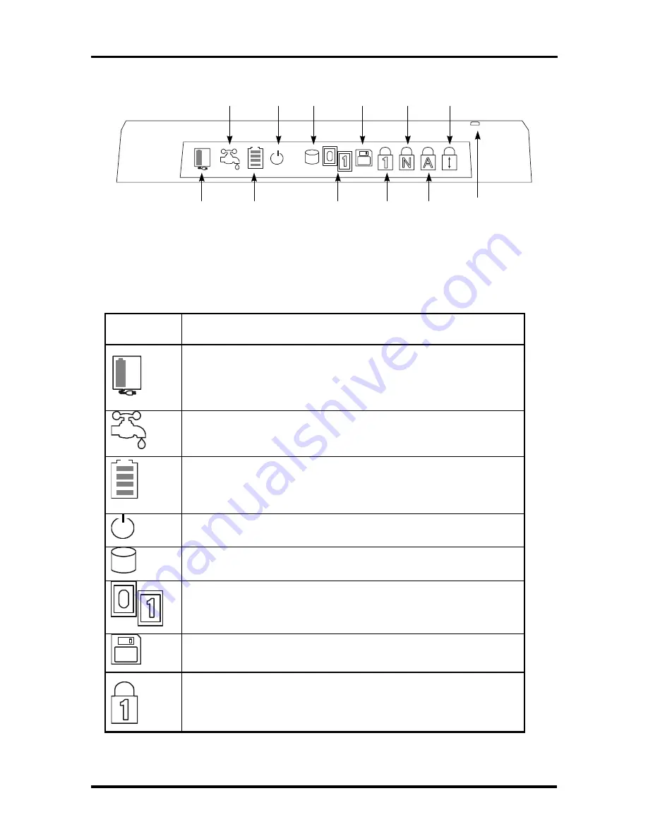
Figure Section 1-4 LCD Status Bar
Table Section 1-3 LCD Status Bar Icons and Description
Graphic
Icons
Description
Activates when system is powered by AC adapter. The battery cell
inside indicate that the battery pack is being charged also and will
disappear when battery has been fully charged. The icon will blink
whenever you first connect the AC adapter and recharging initializes.
Activates if power management feature is enabled. The power
management setup is found on the CMOS SETUP program.
Activates when battery is in use. When battery is already running low,
the icon will start to blink and will generate an intermittent audible
beep. This warns you to save your data files and connect an AC
adapter or swap battery pack.
This icon informs you that the system is in “save-to-RAM” suspend
mode when blinking. Press any key to resume operation.
Activates whenever the hard disk drive is being accessed. To avoid
any data loss, never turn off the computer when this icon is visible.
Activates whenever a PCMCIA card is inserted. The “0” icon will
appear when a PC card is inserted in the upper slot while the “1’ icon
will appear if a card is inserted into the bottom slot.
Activates whenever the floppy disk drive is being accessed. To avoid
any data loss, never turn off the computer when this icon is visible.
This icon, when visible, informs you that the keyboard Pad Lock
function is engaged. The Pad Lock function activates the keyboard’s
embedded editing keys, but only if the Num Lock is disengaged.
Summary of Contents for Versa 550 Series
Page 79: ...4 8 Field Service Guidelines...
Page 127: ...Index 3...


