background image

S

ECTION

4

INSTALLING THE OPTIONAL INTERFACE CARDS

4.1 VoIP Card (VOIPDB-C1)

4.1.1 General

The IP4WW-VOIPDB-C1 daughter board is used to convert the RTP (Real Time Transfer Protocol)
packets via the IP Network and PCM highway. The daughter board is installed on the CPU card.

4.1.2 Unpacking

Table 2-18 VOIPDB-C1 Packing List

Items

List of Contents

QTY

IP4WW-VOIPDB-C1

IP4WW-VOIPDB-C1

1

Ferrite Core (for Ethernet Cable)

1

4.1.3 Installing the VOIPDB-C1 PCB

• Do not remove or install the CPU Card with the power on.
• If Expansion KSU(s) are installed, turn the power on/off in the order of Expan-

sion 2 KSU, Expansion 1 KSU and then Main KSU.

• When the VOIPDB-C1 is installed on the CPU-B1, the NIC card on the CPU

does not function anymore.

1. Turn off the system power and disconnect AC cord.

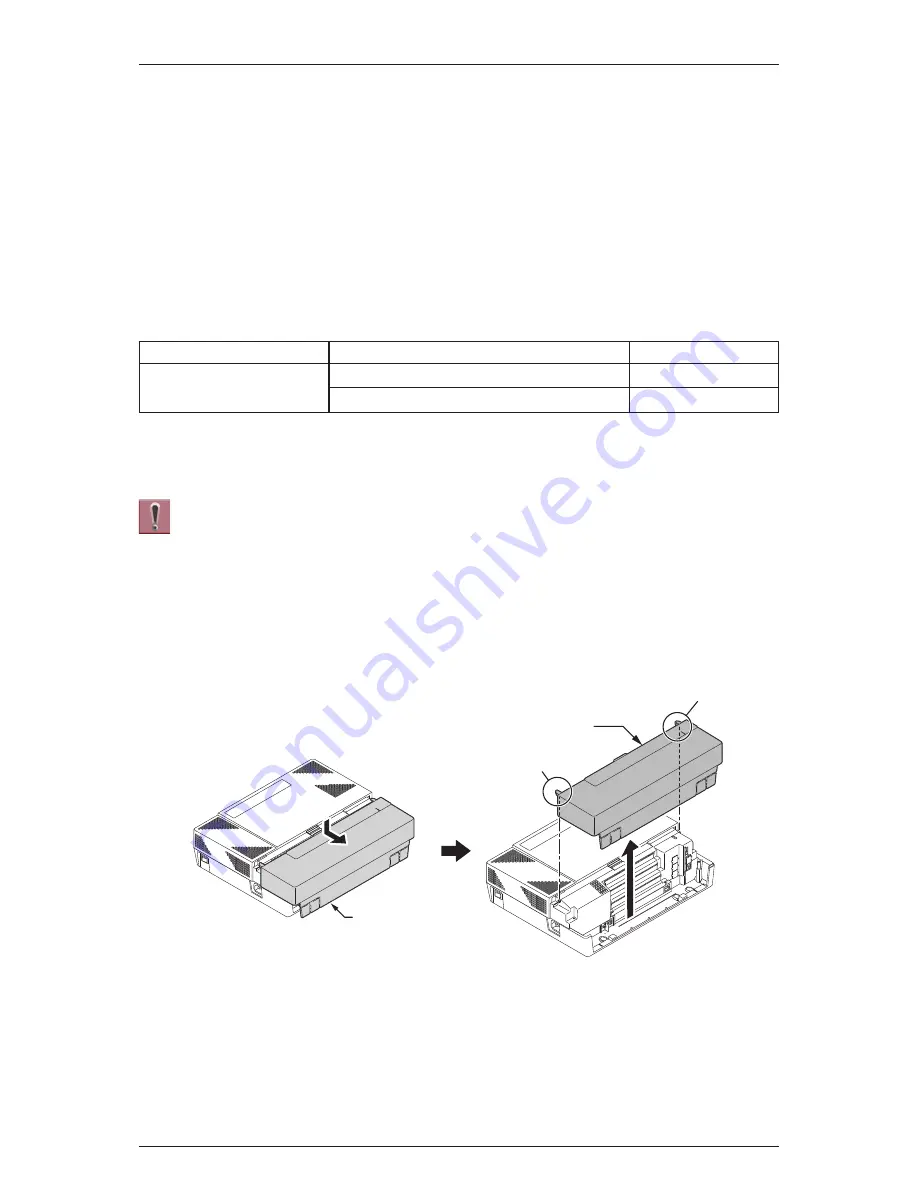
2. Open and remove the Sub-Cover.

3. Loosen two screws and remove the Main-Cover.

Sub-Cover

Sub-Cover

Tab

Tab

Figure 2-79 Removing the Sub-Cover

ISSUE 1.0

SL1100

Installation

2-52

Summary of Contents for SL1100

Page 1: ...rmat changes may occur When viewing and printing this document we cannot guarantee that your specific PC or printer will support all of the fonts or graphics Therefore when you view the document fonts...

Page 2: ......

Page 3: ...Hardware Manual A50 031693 003 NA ISSUE 1 0 September 2011...

Page 4: ...ny time without notice NEC Corporation has prepared this document for use by its employees and customers The informa tion contained herein is the property of NEC Corporation and shall not be reproduce...

Page 5: ...2 5 Wireless DECT Telephones 1 8 2 5 1 DTL 8R 1 Cordless DECT Telephone 1 8 2 5 2 DTL RPT 1 Cordless DECT Telephone Repeater 1 8 2 5 3 ML440 and AP20 Wireless DECT Telephone 1 8 Section 3 SYSTEM CAPA...

Page 6: ...unting One KSU on the Battery Box 2 30 2 7 IP4WW Battery Box to KSU Connection 2 33 2 8 IP4WW Battery Box Fuse Replacement 2 34 Section 3 INSTALLING THE EXPANSION INTERFACE CARDS 2 38 3 1 General 2 38...

Page 7: ...g 2 71 5 8 1 General 2 71 Section 6 INSTALLING WIRELESS DECT TELEPHONES 2 72 6 1 Installing the DTL 8R 1 Cordless DECT Telephone 2 72 6 1 1 Selecting a Location 2 72 6 1 2 Installation Precautions 2 7...

Page 8: ...ion 4 8 3 4 Upgrading the Main Software 4 9 Section 4 LED INDICATIONS 4 12 Chapter 5 Specifications Section 1 SYSTEM CAPACITY 5 1 Section 2 SYSTEM SPECIFICATIONS 5 3 2 1 General Precautions 5 3 2 2 En...

Page 9: ...2 18 Cable Requirements 5 7 TABLE OF CONTENTS Hardware Manual v...

Page 10: ...e Specifications 2 68 Table 2 23 RJ 61 General Purpose Door Unlock Relay Control Connector J7 2 69 Table 2 24 General Purpose Door Unlock Relay Specifications 2 69 Table 2 25 External Paging Output Sp...

Page 11: ...gure 2 22 Analog Extension Cabling 2 15 Figure 2 23 Cabling 2 16 Figure 2 24 Sub Cover 2 16 Figure 2 25 Dimension of the IP4WW Battery Box 2 18 Figure 2 26 Removing the Front Cover 2 19 Figure 2 27 Di...

Page 12: ...DB B1 2 48 Figure 2 76 Connector of 1PRIU C1 2 49 Figure 2 77 Switches and LEDs Location of 1PRIU C1 2 50 Figure 2 78 1PRIU C1 LED Indication Pattern of Layer 1 on T1 Unit 2 51 Figure 2 79 Removing th...

Page 13: ...l Mounting 2 78 Figure 2 129 Wrapping the AC Adapter Cord Around the Strain Relief 2 78 Figure 2 130 Placing the Charging Unit on the Wall 2 79 Figure 2 131 Attaching the Belt Clip to the Handset 2 79...

Page 14: ...ery 4 4 Figure 4 6 Removing the Sub Cover 4 4 Figure 4 7 Disconnecting the AC Power Cord 4 5 Figure 4 8 Removing the Main Cover 4 5 Figure 4 9 Removing the CPU Card 4 6 Figure 4 10 Location of Lithium...

Page 15: ...art 68 rules A plug and jack used to connect this equipment to the premises wiring and telephone network must comply with the applicable FCC Part 68 rules and requirements adopted by the ACTA A compli...

Page 16: ...affidavit To comply with state tariffs the telephone company must be given notification prior to connection In some states the state public utility commission public service commission or corporation...

Page 17: ...responsible for equipment requiring AC power should consider including an advisory notice in their customer information suggesting the customer use a surge arrestor Telephone companies report that el...

Page 18: ...ot prevent degradation of service in some situations Repairs to certified equipment should be coordinated by a representative designated by the supplier Any repairs or alterations made by the user to...

Page 19: ...returned to a federal or state approved sealed lead battery recycler This may be where the batteries were originally sold or a local seller of automotive batteries Contact your local waste management...

Page 20: ...ately to allow proper treatment recovery and recycling These products should be taken to a designated facility where the best available treatment recovery and recycling techniques are available Separa...

Page 21: ...censed battery dealer or a designated collection facility Do not incinerate batteries This product uses Lithium batteries Do not use any other type For an overview of the location of batteries used in...

Page 22: ...Memo ISSUE 1 0 SL1100 Regulatory R 8...

Page 23: ...100 is also equipped to support Digital Network PRI T1 and IP Trunks SIP or IP extensions Also the SL1100 initially bundles Voice Mail and MEMDB IP VoIP PSTN ISDN DSS Console Analog Telephone FAX Door...

Page 24: ...00111 IP4WW VOIPDB C1 16 channel VOIP on CPU 1100112 IP4WW CFVMS C1 Compact Flash for VRS and InMail Approx 15 hours VRS 4ch default InMail 2ch default 1100113 IP4WW CFVML C1 Compact Flash for VRS and...

Page 25: ...following are included with the KSU CPU with main software CPU B1 Power supply 110V 240V 1 External backup battery connector 2 mounting spaces for 080E 008E 1PRIU 8 digital and 4 analog extension I F...

Page 26: ...cannot be used in a stand alone mode 2 1 3 IP4WW EXIFB C1 Using a Cat5 cable EXIFB C1 card installed in the Main KSU is individually connected to each EXIFE C1 card Expansion KSU Install this card to...

Page 27: ...IDB can be mounted on this card Install this card to the expansion card slot at Main Expansion KSU One analog trunk daughter board connection 2 2 3 IP4WW 4COIDB B1 The 4COIDB provides four analog trun...

Page 28: ...l InMail Approx 40 hours 2 4 Multiline Telephones and Optional Equipment 2 4 1 IP4WW 12TXH B TEL The 12TXH B TEL is a 2 wire digital multiline telephone featuring Programmable keys 12 Soft Keys 4 LCD...

Page 29: ...ing kit IP4WW WALL MOUNT UNIT Optional 2 4 4 IP4WW 60D DSS B The DSS console gives a multiline terminal user a Busy Lamp Field BLF and one button access to extensions trunks and system features Mainly...

Page 30: ...R 1 Cordless Handset 2 5 2 DTL RPT 1 Cordless DECT Telephone Repeater DTL RPT 1 is a repeater to extend the coverage area of DTL 8R 1 Cordless DECT telephone system in all directions 2 5 3 ML440 and A...

Page 31: ...84Mx3 008Ex9 2W DSS Console 12 Connect to digital extension Port at 084M 080E Doorphone 2 4 6 2DPH I F on 084M analog extension port 3 4 Alternative use with SLT SIP MLT SIP Std terminal 64 VM VRS Cha...

Page 32: ...MFC sender 3 2 KSU Capacity System image of KSU capacity ISDN Trunk Extension is shown as below Expansion Interface Card x 2 Mother Board Expansion Interface Card x 2 Mother Board Mother Board 084M 1...

Page 33: ...SU 080E or 008E 2nd opt slot 2nd opt slot 12 20 28 Extension 080E or 008E 4COIDB 1st opt slot 1st opt slot 1st opt slot Example 2 084M 4Trk 8Ext 4Trk 8Ext Example 3 084M 4Trk 8Ext 8 4 084M 4COIDB 1 KS...

Page 34: ...x 1 76 64 32 32 8 4 4 1228M KSU 1228ME EXP 1st exp KSU 1228ME EXP 2nd exp KSU 20 40 68 Extension 080E or 008E 1st opt slot 1 KSU 12 20 PRI 2nd opt slot Example 2 084M PRI x 1 24 1 KSU 12 PRI 1st opt...

Page 35: ...available Make sure you have a building plan showing common equipment extensions the telecom demarca tion and earth ground location The installation site must meet the following site environmental re...

Page 36: ...all Mounting Template 1 1 2 Installing the Main KSU 1228M B KSU The Main KSU has a CPU B card an eight digital and four analog extension Interface a control relay circuit for External devices and two...

Page 37: ...e 4 17 Inserting the CF Card on page 4 10 and Table 4 2 CPU LED Indications on page 4 12 1 3 Wall Mounting the KSU s 1 3 1 KSU Dimensions For Dimensions of the 1228M B and 1228ME B KSUs refer to Figur...

Page 38: ...ansion KSU s must be considered as above or as the next figure When KSU is mounted on the Battery Box it cannot be wall mounted for vertically as above In the case the KSU is mounted on Battery Box mu...

Page 39: ...one KSU on the Battery Box on page 2 30 1 Place the attached template on the wall to mark the four screw positions 2 Install four screws into the wall The screw heads must stand off from the wall abo...

Page 40: ...he center of the Sub Cover and slide it outward 4 Pull out the Sub Cover by pushing out the tabs 285 mm 11 221 285 mm 11 221 180 mm 7 087 2 5 mm 0 098 3 5 mm 0 138 Figure 2 6 Screw Positions Sub Cover...

Page 41: ...eneral Each Expansion KSU is connected to the Main KSU individually The EXIFB C1 card must be installed in the Main KSU 1228M B 1 4 2 Unpacking EXIFB C1 Unpack the EXIFB C1 and check it against physic...

Page 42: ...Debug Purpose Not used 1 4 4 Installing the EXIFB C1 PCB Do Not Power on until all installations have been completed 1 Turn off the system power and disconnect the AC cord from KSU 2 Open and pull ou...

Page 43: ...7 Cut and remove the Plastic Knockouts as needed for Expansion KSU 8 Replace the Main Cover and fasten two screws Two screws Hooks Main Cover Figure 2 13 Removing the Main Cover CPU support CPU suppo...

Page 44: ...attached to the Expansion KSU The cable must pass two times two rounds through the Ferrite Core refer to Figure 2 17 Connection of KSUs on the next page Ferrite Core is attached with the Expansion KS...

Page 45: ...1 1228ME B Exp KSU No 2 1228ME B Main KSU 1228M B Bottom View Bottom View Bottom View EXIFE C1 PCB CPU card EXIFE C1 PCB EXIFB C1 PCB EXP 2 EXP 1 EXP EXP LAN Figure 2 17 Connection of KSUs Ferrite Cor...

Page 46: ...ent of a lightning strike 1 5 2 AC Power Requirement A dedicated 100V 120V 220V 230V 240V 50 60Hz circuit located within two meters of the KSU is required A separate dedicated AC outlet is necessary f...

Page 47: ...switch and AC power inlet are located at the left side of each KSU The AC power cord is connected to the AC inlet and the commercial AC power socket Do not plug in AC power cord if the KSU Cover is r...

Page 48: ...ithin each KSU provides two RJ61 modular jacks for digital extension 8ports and one for analog extensions 4ports Before plugging in the Multiline Telephone DSS Console Single line Telephone or Doorpho...

Page 49: ...03 to Door Phone is required when connecting a Door phone Box or Sensor device 1 6 4 1 Connectors The following table shows the pin outs for the RJ 61 cable connector for Digital Analog extension con...

Page 50: ...1 R1 Ring for port 1 5 T1 Tip for port 1 T1 Tip for port 1 6 R2 Ring for port 2 R2 Ring for port 2 7 R3 Ring for port 3 R3 Ring for port 3 8 R4 Ring for port 4 R4 Ring for port 4 1 6 5 Cable Routing a...

Page 51: ...amage to equipment do not install the Topaz Battery Box DX2E 32i NX7E Battery Box to the SL1100 system 2 2 Unpacking Unpack the IP4WW Battery Box and check it against the following list Inspect for ph...

Page 52: ...ational LTD The Battery must be UL recognized product Number of Batteries per Box 2 Backup Duration Estimated 1 hour 2 5 Battery Installation Before floor mounting or wall mounting the IP4WW Battery B...

Page 53: ...e cable is plugged already 3 Loosen the screw and lift the Batt Stopper Front Cover Two screws with stopper Figure 2 26 Removing the Front Cover Battery Connection Cable Fuse Unit Figure 2 27 Disconne...

Page 54: ...n two screws and remove the Battery tray cover 6 Remove two screws and remove the Battery tray bracket Screw Batt Stopper Figure 2 28 Batt Stopper Battery tray Figure 2 29 Pulling out the Battery Tray...

Page 55: ...ttery cables Two screws M3 X 8 Two screws with stopper Battery tray cover Battery tray bracket Figure 2 30 Remove the Battery Tray Bracket Two screws M3 X 8 Two batteries Battery tray bracket Figure 2...

Page 56: ...en installing the Battery tray cover Write down the year and month of the next battery replacement in the label on Front cover 11 Insert the Battery tray into the Battery Box Terminal black Terminal b...

Page 57: ...place and secure with screw 13 Plug the Battery Connection Cable into the Fuse unit Battery tray Figure 2 34 Inserting the Battery Tray Screw Batt Stopper Figure 2 35 Secure Batt Stopper Bracket ISSU...

Page 58: ...ox 2 6 1 Floor Mounting the IP4WW Battery Box Battery box can be mounted on the floor using the FM WM Base F FM WM Base R and WM Support Note FM Floor Mount and WM Wall Mount 1 Assemble the FM WM Base...

Page 59: ...he FM WM Base to the floor 4 Using the four hooks on the FM WM Base mount the IP4WW Battery Box on the Base WM Support FM WM Base R FM WM Base F Figure 2 38 Bases and Support of the Battery Box Four A...

Page 60: ...ed to the wall using the FM WM BASE Ensure that enough space is available to allow the installation of additional KSU Plywood should first be installed on the wall where the Battery Box will be positi...

Page 61: ...page for required spacing before drilling holes for 10 mm anchor bolts locally procured Mark and drill the four holes required to install the FM WM Base 3 Using anchor bolts secure the FM WM Base to...

Page 62: ...Maintenance space Anchor bolt location Anchor bolt location Four Anchor bolts M10 mm 0 394 150 mm 5 906 343 mm 13 504 500 mm 19 685 460 mm 18 110 Front side Wall AC inlet side Figure 2 43 Wall Mount S...

Page 63: ...pplied screw M3x6 with washer secure the back plane of the Battery Box to the FM WM Base Front Cover Two screws with stopper Figure 2 44 Removing the Front Cover IP4WW Battery Box Square hole Hooks Ho...

Page 64: ...ounted on the Battery Box 1 Loosen two screws and remove the Front Cover of the Battery Box 2 Loosen two screws and remove the L Bracket Two screw holes Use either one Front view Figure 2 46 Securing...

Page 65: ...n the next page 4 Insert tabs on Battery Box into holes on L Bracket Secure the L Bracket to the Battery Box using two screws 5 Using two screws M4x8 secure the WM Hook to the L Bracket 6 Using two an...

Page 66: ...the KSU on the screw heads 8 Hold open the Sub Cover of the KSU and fasten two screws to mount the KSU Two screws M4 X 8 Two screws M4 X 8 Anchor Bolts L Bracket WM Hook Figure 2 49 Securing the L Bra...

Page 67: ...stalled turn the power on off in the order of Expan sion 2 KSU Expansion 1 KSU and then Main KSU 1 Power off the KSU and disconnect AC cord 2 Open the Sub Cover of the KSU 3 Cut and remove Plastic Kno...

Page 68: ...tion Be careful not to burn yourself on the heated fuse The blown fuse may be heated soon after blowing If Expansion KSU s are installed turn the power on off in the order of Expan sion 2 KSU Expansio...

Page 69: ...the Fuse Unit guides slide the Fuse Unit into the Battery Box Battery Connection Cable Fuse Unit Figure 2 55 Disconnecting the Battery Connection Cable Screw Fuse Unit Figure 2 56 Loosen the Fuse Unit...

Page 70: ...f to holes A to F on Battery Box Slide the Front Cover into position and tighten the two screws Fuse Unit guide Fuse Unit Figure 2 58 Install the Fuse Unit Screw Fuse Unit Figure 2 59 Securing the Fu...

Page 71: ...b a A B C D E F c d e f Front cover Two screws with stopper Figure 2 61 Installation of the Front Cover ISSUE 1 0 SL1100 Hardware Manual 2 37...

Page 72: ...E B1 4COIDB B1 Yes Yes Yes 3 2 Unpacking Unpack the 080E B1 008E B1 4COIDB B1 1PRIU C1 and check it against the following list Inspect for physical damage Table 2 10 Expansion Card Packing List Items...

Page 73: ...the order of Expan sion 2 KSU Expansion 1 KSU and then Main KSU 1 Turn off the system power and disconnect the AC cord from KSU 2 Open and remove the Sub Cover 3 Loosen two screws and remove the Main...

Page 74: ...and fasten two Metal spacers into the specified holes Both Nylon and Metal spacers are provided with 080E 008E 1PRIU Expansion Interface Card 1st PCB J21 J1 Nylon Spacers Metal Spacers Screw position...

Page 75: ...e Plastic Knockouts as required for each Expansion interface card Expansion Interface Card 2nd PCB J1 J2 Nylon Spacers Metal Spacers Screws Expansion Interface Card 1st PCB Screw position Both sides a...

Page 76: ...ain Cover and fasten two screws Main Cover Plastic Knockouts EXP 1st PCB EXP 2nd PCB Figure 2 67 Plastic Knockouts Two screws Hooks Main Cover Figure 2 68 Replacing the Main Cover ISSUE 1 0 SL1100 Ins...

Page 77: ...70 Installing the 4COIDB B1 on this page 4 Attach the 4COIDB Label to the specified position on the 084M B1 080E B1 008E B1 PCB The 4COIDB B1 cannot be mounted on the 1PRIU C1 PCB 5 Mount the 4COIDB...

Page 78: ...requency generating device Use cable protectors in case the cables run on the floor Aerial distribution wiring is not allowed Trunks must be installed with lightning protectors 084M B1 080E B1 008E B1...

Page 79: ...one or Doorphone ensure all Main and Expansion KSUs are powered off DSX Terminal does not work properly when it connected Exit Help Flash Clear Back ABC GHI JKL MNO PQRS TUV WXYZ DEF Hold Speaker 1 2...

Page 80: ...4 2 T3 Tip for port 3 3 T2 Tip for port 2 4 R1 Ring for port 1 5 T1 Tip for port 1 6 R2 Ring for port 2 7 R3 Ring for port 3 8 R4 Ring for port 4 3 4 2 Cabling IP4WW 008E B1 This IP4WW 008E B1 PCB pr...

Page 81: ...nec tions Table 2 12 RJ 61 Analog Pin Outs J101 J102 Pin No SLI 1 4 J101 SLI 5 8 J102 2 Wire Analog Extension port Connector RJ 61 87654321 1 T4 Tip for port 4 2 T3 Tip for port 3 3 T2 Tip for port 2...

Page 82: ...rt Connector RJ 61 PF1 J3 PF Tel Port Connector RJ 61 87654321 1 T4 Tip for port 4 2 T3 Tip for port 3 3 T2 Tip for port 2 4 R1 Ring for port 1 R1 Ring for port 1 5 T1 Tip for port 1 T1 Tip for port 1...

Page 83: ...tch Setting The following figure shows the location of the switches and LEDs on the IP4WW 1PRIU C1 Card 1 Set the switches J6 to J9 according to the system referring the Table 2 15 Switch Setting of 1...

Page 84: ...tus Remarks Live LED D4 Green Busy LED D3 Red On On System Initializing Flash 1s On The assignment of the unit is refused When you exceed the system capacity When the main software version is not matc...

Page 85: ...reen a red LED and a green LED flash on and off 3 times simultane ously RAI RAI Remote Alarm Indication Yellow Alarm Following an alarm blink red green red green a green LED flashes on and off twice N...

Page 86: ...C1 1 Ferrite Core for Ethernet Cable 1 4 1 3 Installing the VOIPDB C1 PCB Do not remove or install the CPU Card with the power on If Expansion KSU s are installed turn the power on off in the order of...

Page 87: ...to J5 connector on the CPU card Two screws Hooks Main Cover Figure 2 80 Removing the Main Cover CPU support CPU card 084M B1 at 1228M KSU A Figure 2 81 Removing the CPU Card CPU card J5 VOIPDB C1 PCB...

Page 88: ...VoIP connector then replace the Main Cover and fasten two screws 8 Connect the VOIPDB C1 to an Switching hub using an LAN Cable CPU support 084M B1 at 1228M KSU CPU card Figure 2 83 Installing the CP...

Page 89: ...ons on this page Each LED is listed with its associated function and operational status Table 2 19 VOIPDB LED Indications LED Function LED Status Operation status ACT Link activity or data transmissio...

Page 90: ...ing updated 4 2 Installing the CF Card CFVMS CFVML Do not remove or install the CPU Card with the power on If Expansion KSU s are installed turn the power on off in the order of Expan sion 2 KSU Expan...

Page 91: ...lamp field Red Green 24 Busy lamp field Red Green Display 24 digit x 3 lines with Backlit Handsfree Full duplex Wall Mount Kit Yes Built in Yes Optional SoftKeys Yes Backlit Dial Pad Yes Incoming LED...

Page 92: ...t for two different heights Low High 5 1 2 1 Low Position Setting 1 Turn telephone over button side down 2 Adjust the legs to desired height 3 Lead the Line and Handset cords through the applicable gr...

Page 93: ...cords through the applicable grooves Refer to Figure 2 90 Cabling of Multiline Telephone on the previous page Leg Leg Stopper Figure 2 91 Setting for High Position Leg High position Figure 2 92 Leg S...

Page 94: ...o the bottom panel as shown 2 Remove the switch hook from the unit Turn the tab toward the top Then slide the hook switch into position Refer to Figure 2 95 Hook Switch Hanger on the next page Leg Bot...

Page 95: ...e wall Hook switch hanger Hook switch hanger Figure 2 95 Hook Switch Hanger 7 9 5 mm 0 28 0 37 83 5 mm 3 287 Minimum 10 mm 0 39 3 4 mm 0 12 0 16 1 3 mm 0 04 0 12 Figure 2 96 Wall Mount Screw Guide Wal...

Page 96: ...straight cable used for connection to the PC to the PC X connector and to the PC 5 2 3 Applying Power to the IP Multiline Telephone IP Multiline Telephone IP4WW 24TIXH C1 supports two different power...

Page 97: ...nsion for the DSS Console is assigned using system programming For the settings refer to the SL1100 Features Specifications Manual 5 3 1 DSS Console Leg Adjustment The DSS Console provides the leg for...

Page 98: ...s page 5 3 2 Wall Mounting the DSS Console 1 Lift the leg and lead the cable through the applicable grooves Refer to Figure 2 104 Cabling for Wall Mount on the next page Lower leg to stowed position L...

Page 99: ...andset Like using Handsfree using the headset frees up the user s hands for other work However Headset Operation provides privacy not available from Handsfree Bottom view Leg Figure 2 104 Cabling for...

Page 100: ...rogramming 5 5 Installing the Doorphone Box 5 5 1 Wall Mounting the Doorphone 1 Remove the screw on the front of the Doorphone Box 2 Remove the Wall Mount bracket from the Doorphone Box 3 Connect the...

Page 101: ...the Upper housing and tighten the screw Screw Upper housing Connect cable Wall mount bracket Screw terminals Figure 2 109 Doorphone Box and Bracket Upper housing Hook Attached screws Hole Screw Wall...

Page 102: ...ifications Table 2 22 Doorphone Interface Specifications Item Specification Output Impedance 600 Output Level Nominal 250 mV 10 dBm Maximum Output 400 mV RMS T R Doorphone Modular Cable 2 wire Straigh...

Page 103: ...lock Relay Control Connector J7 Pin No Connection 87654321 RY1 2 J7 1 2 3 Relay 2 4 Relay 1 5 Relay 1 6 Relay 2 7 8 Table 2 24 General Purpose Door Unlock Relay Specifications Item Specification Rated...

Page 104: ...system programming 5 7 2 External Paging Output Specifications Table 2 25 External Paging Output Specifications Item Specification Output Impedance 600 1kHz Output Level Nominal 250 mV 10 dBm Maximum...

Page 105: ...1 General SMDR Station Message Detail Recording provides a record of the system s outside calls Typically the record outputs to a customer provided SMDR device such as PC via LAN port J3 on the CPU ca...

Page 106: ...the same time The Handset and Base Station must have the original ID that is written on each unit at the factory 6 1 1 Selecting a Location Select a location for the DTL 8R 1 Cordless DECT to avoid e...

Page 107: ...telephone 6 1 3 Connecting the Telephone Cords When connecting the telephone cords observe the following precautions Never install telephone wiring during a lightning storm Never touch bare telephone...

Page 108: ...is plug fits in the power outlet only one way If you cannot insert the plug fully in the outlet try reversing the plug Refer to Figure 2 120 Polarized Plug on this page If you cannot plug the AC adapt...

Page 109: ...al multiline terminal into the PHONE jack Place the telephone cords inside the molded channels on the bottom of the wall mount stand 5 Plug the other end of the short telephone cord into the modular w...

Page 110: ...pes or other items behind the mounting location that could cause a hazard when inserting screws into the wall Make sure the wall material can support the weight of the base unit Use 10 screws with anc...

Page 111: ...Place the telephone cords inside the molded channels on the bottom of the wall mount stand 5 Place the base unit on the posts of the wall screws and push down until it is firmly seated Figure 2 125 I...

Page 112: ...hazard when inserting screws into the wall Make sure the wall material can support the weight of the charging unit Use 10 screws with anchoring devices suitable for the wall material where the chargin...

Page 113: ...to a belt or pocket for convenient portability 1 Slide the clip into the tab slots Press firmly until it snaps into place The belt clip fits snugly onto the handset 2 To remove the clip press the reta...

Page 114: ...move the battery cover by pressing the latch and sliding the cover down and off of the handset 2 Slide the battery pack down into the handset It may be necessary to remove the old battery at this time...

Page 115: ...ess DECT for the first time Charge the battery pack without interruption for five to eight hours 6 1 11 Charging Spare Battery Packs The DTL 8R 1 Cordless DECT is equipped with a battery charger for c...

Page 116: ...ea overlaps the coverage area of the base the base can hand off calls to the repeaters as the user moves from one coverage area to another When connected to the repeater the mobile handset operates th...

Page 117: ...base supports up to six repeaters so you can extend coverage in all directions including through floors and ceilings Figure 2 137 Single Repeater Attached to Base Figure 2 138 Six Repeaters Attached t...

Page 118: ...hone to 0000 consult the manual that came with your base for more information After you reset the PIN make sure to register the handset you used back to the base station 6 2 1 2 Automatic Registration...

Page 119: ...ifferent base you must reset the repeater 6 2 1 4 Registration for a Daisy Chain Layout Registering the repeaters to operate in a daisy chain or sequential layout requires network adminis trator acces...

Page 120: ...may be interference from electronic devices or the signal might be blocked by thick walls or metal objects Try moving the repeater to another location 6 2 2 4 Installing the Repeater Be sure the wall...

Page 121: ...s and floors Incorrect Installation Figure 2 141 Incorrect Installation on this page illustrates repeaters that are incorrectly installed Correct Installation Figure 2 142 Base Coverage Area on this p...

Page 122: ...llation problems refer to the Cordless DECT Repeater Guide DTL RPT 1 6 2 5 Maintenance For user maintenance of the repeater refer to the Cordless DECT Repeater Guide DTL RPT 1 6 3 Installing the ML440...

Page 123: ...C adapter and a standard Ethernet to PoE adapter Contact Customer Service Follow the steps below to connect the base station 1 Connect a standard Ethernet cable Cat 5 or higher to the Ethernet PoE jac...

Page 124: ...nit OR initializing and connecting to the network Orange Briefly on Powering on Orange Flickering Stage in base flash memory rewrite at the end of the base firmware update Red Blinking Factory reset w...

Page 125: ...out 1 4 inch of space between the screw head and the wall 4 Connect the Ethernet cable and route the cord as shown in Figure 2 146 Base Mounting Dimensions on this page 5 Place the base over the screw...

Page 126: ...re 2 147 Handset Front View on this page provides a front view of the handset and Figure 2 148 Charger Top View on the next page provides a top view of the charger Figure 2 147 Handset Front View ISSU...

Page 127: ...arger AC adapter to connect the charger s AC jack to a standard 120 V AC power outlet 3 Place the handset in the charger with the display facing forward The HANDSET STATUS LED should turn on if it doe...

Page 128: ...Charger on the previous page Charge each battery completely about 10 hours before use 6 3 3 2 Powering on the Handset To power up the handset press and hold End until the display flashes once about 3...

Page 129: ...Lithium battery protection sheet before starting up the system If Expansion KSU s are installed turn the power on off in the order of Expansion 2 KSU Expansion 1 KSU and then Main KSU 1 2 Starting Up...

Page 130: ...n 2 KSU Expansion 1 KSU and then Main KSU To perform a Cold Start 1 Set the power switch to off position 2 Open the Sub Cover on the Main KSU and identify the LOAD button S1 location on the CPU card 3...

Page 131: ...customer data is loaded from RAM memory If Expansion KSU s are installed turn the power on off in the order of Expan sion 2 KSU Expansion 1 KSU and then Main KSU To perform a Hot Start 1 Turn the syst...

Page 132: ...3 Saving Backup the Customer Data When the installer system administrator exits from the programming mode the system will automati cally save the customer data to the on board memory which is backed u...

Page 133: ...ited by the PC 2 4 Loading the Customer Data The backed up customer data can be loaded to the system by CF Card 1 Turn the power off insert the Customer Data CF card into the CF Slot on VMDB CPU card...

Page 134: ...to the next PRG 5 Remove the CF card and exit from the Program Mode CPU card CF Slot CN2 CF card VMDB Figure 3 13 Inserting the CF card Program Mode Base Service OP1 OP2 90 04 01 Data Load YES 1 1 Fig...

Page 135: ...AC or DC for battery backup power Always use the Power Switch on the Main Expansion KSU All calls in progress will be cut off when the system is powered off and if the Power Failure is set the applic...

Page 136: ...Memo ISSUE 1 0 SL1100 System Start Up 3 8...

Page 137: ...ansion KSU s are installed turn the power on off in the order of Expan sion 2 KSU Expansion 1 KSU and then Main KSU 1 Turn off the system power and disconnect AC cord 2 Open and remove the Sub Cover 3...

Page 138: ...8 A on 084M B1 PCB 5 Replace the Main Cover and fasten two screws Two screws Hooks Main Cover Figure 4 2 Removing the Main Cover Top View 084M B1 FUSE 8 A 250 V Figure 4 3 Exchanging the Fuse ISSUE 1...

Page 139: ...Two screws Hooks Main Cover Figure 4 4 Replacing the Main Cover ISSUE 1 0 SL1100 Hardware Manual 4 3...

Page 140: ...y CR2032 NEC recommends that a backup of the customer data is performed before powering off the system either PCPro file or CF card backup in order to replace the backup battery Risk of explosion if t...

Page 141: ...ed otherwise the Main Cover cannot be opened 4 Loosen two screws and remove the Main Cover 5 Press tab A and lift the CPU support bracket 6 Remove CPU card from the Main KSU Disconnect AC Power Cord F...

Page 142: ...socket The polarity symbol must be on top as illustrated in following figure CPU support CPU card 084M B1 at 1228M KSU A Figure 4 9 Removing the CPU Card Battery socket Conductor side J12 CPU card Fi...

Page 143: ...and close the CPU support bracket 10 Replace the Main Cover and Sub Cover Lithium battery Socket Figure 4 12 Inserting the Lithium Battery CPU support CPU card 084M B1 at 1228M KSU Figure 4 13 Instal...

Page 144: ...ware Version Confirmation The main system software version is confirmed by the following operation at the display type Multiline Telephone The following steps assume that program 15 02 60 is set to Ad...

Page 145: ...1 KSU and then Main KSU 1 Power off the system and disconnect the AC cord from the KSU 2 Remove the Sub Cover 3 Loosen two screws and remove the Main Cover 4 Insert the CF card with the new main syst...

Page 146: ...he CPU card has the following indications approxi mately two minutes Table 4 1 Status LEDs LED No Indication Remarks D2 Flashing Red D3 Flashing Red D4 Flashing Red D5 Off 10 Turn the power off and re...

Page 147: ...new software version number press the Navigation key on any display telephone to view the system version number see Main Software Version Confirmation on page 4 8 The existing system data in the flas...

Page 148: ...Blinking Off System Starting Up On Off Off Off Off Boot is starting On Off Off Off Blinking Initializing the disk or formatting Blinking Off Off Off Off Reading System Program Blinking Off On Access...

Page 149: ...t 24 48 72 Max 24 KSU 084M 080Ex2 SLT 28V 20 40 60 1KSU 084M 008Ex2 2KSU 084Mx2 008Ex6 3KSU 084Mx3 008Ex9 2W DSS Console 12 Connect to digital extension Port at 084M 080E Doorphone 2 4 6 2DPH I F on 0...

Page 150: ...34 Modem 1 1 circuit on CPU B1 VMDB Conference Circuits 32 Max 16 parties per Conference DSP Resource 1 32 For 1228M KSU DSP on CPU 32 64 For 1228ME EXP 32ch DSP on each EXIFE C1 DSP Sender 2 128 1 S...

Page 151: ...Telephones Temperature 0 to 40 degree C 32 to 104 degree F Humidity 10 to 90 non condensing Doorphone Box Temperature 20 to 60 degree C 4 to 140 degree F Humidity 20 to 80 non condensing 2 4 Site Req...

Page 152: ...26 BTU 3 KSU Total 1578 BTU Main KSU 526 BTU 3 KSU Total 1578 BTU Main KSU 532 BTU 3 KSU Total 1596 BTU 2 6 Electrical Specifications Power Supply KSU Table 5 4 Electrical Specifications of KSU Item S...

Page 153: ...cations Unit Width Depth Height Weight IP4WW VOIPDB C1 66 mm 2 60 in 138 mm 5 43 in 18 mm 0 71 in 0 05 kg 1 76 oz IP4WW 080E B1 160 mm 6 30 in 198 mm 7 80 in 32 mm 1 26 in 0 17 kg 6 00 oz IP4WW 008E B...

Page 154: ...ce 600 1 kHz Input Level Nominal 250 mV 10 dBm Maximum Input 1 V RMS 2 15 External Sensor Device Interface Specifications Table 5 13 External Sensor Device Interface Specifications Applied Voltage dur...

Page 155: ...ing for SLT connections 2 18 Cable Requirements Table 5 15 Cable Requirements Device Cable Type Cable Run Length Multiline Telephone 24 AWG 0 5 mm 300 m 984 3 ft Multiline IP Telephone CAT5 Straight C...

Page 156: ...Memo ISSUE 1 0 SL1100 Specifications 5 8...

Page 157: ...Memo ISSUE 1 0 SL1100 Hardware Manual 5 9...

Page 158: ...Hardware Manual NEC Corporation ISSUE 1 0...

Reviews: