Figure -25 Attaching the Rails
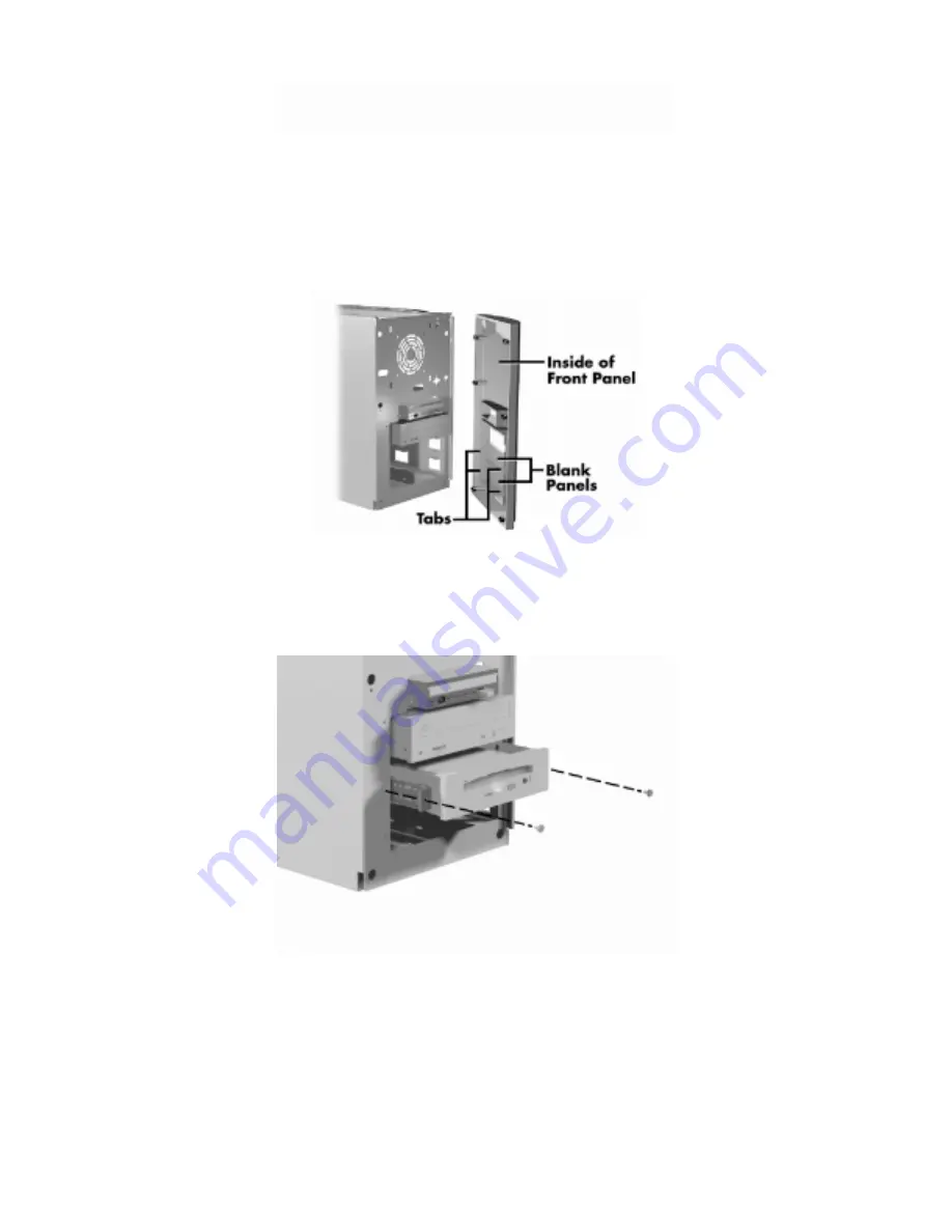
If you are installing an accessible device, locate the blank panel on the front panel corresponding to the
device slot in the system.
Remove the blank panel by pressing the panel tabs from inside the panel and pushing the panel out.
Figure -26 Locating the Blank Panel Tabs
Insert the connector end of the device into the device slot in the system unit and secure the device with the
two slot cover screws removed earlier.
Figure -27 Securing the Device
Connect the device cables (see "Device Cabling").
Replace the front panel as follows:
Align the front panel plugs with the system unit holes.
Summary of Contents for READY ES PRO
Page 17: ......
Page 34: ...Turn on the serial device and the computer Figure 31 Connecting an RS 232C Cable...
Page 59: ...Figure 5 15 Illustrated Parts Breakdown 980428mc...
Page 66: ......


