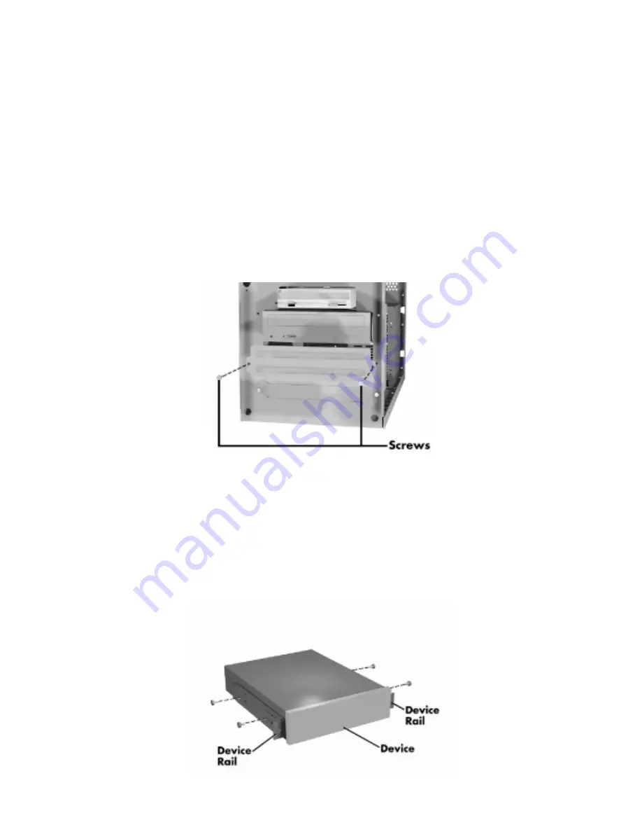
NOTE: If your 5 1/4-inch device comes with drive rails, do not attach them. Remove any rails attached. See
the documentation that comes with the device.
Remove the system unit cover.
Remove the front panel by carefully pulling it off the front of the system unit. Use an even amount of pressure
around the edges of the panel.
NOTE: The front panel is secured with six locking plugs.
Remove the two screws holding the slot cover and the two rails to a device slot in the system.
If you are installing a hard disk in the 5 1/4-inch slot, keep the slot cover handy.
Otherwise, store the slot cover. Replace the cover if you remove the device from the slot.
Figure -24 Removing a Slot Cover
Attach the two rails that come with your system to the sides of the device. Use the four screws that come with
the device.
If you are installing an accessible device, attach the rails to the device so that the front of the device extends
outside the chassis.
The front of a typical device should be even with the blank panels on the front of the system.
Summary of Contents for READY ES PRO
Page 17: ......
Page 34: ...Turn on the serial device and the computer Figure 31 Connecting an RS 232C Cable...
Page 59: ...Figure 5 15 Illustrated Parts Breakdown 980428mc...
Page 66: ......


