


3-12 Disassembly and Reassembly
RIMM Memory Modules
See the following sections for procedures on removing or installing a RIMM memory module or
a continuity module. See Section 4, “System Boards,” for RIMM module upgrade paths and
guidelines for selecting RIMM modules.
Removing a RIMM or Continuity Module
Remove a RIMM module or a continuity module as follows.
Before opening the system and before handling boards or RIMM
memory modules, reduce static discharge by touching the chassis.
1.
Remove the cover (see “Removing the Cover” earlier in this section).
2.
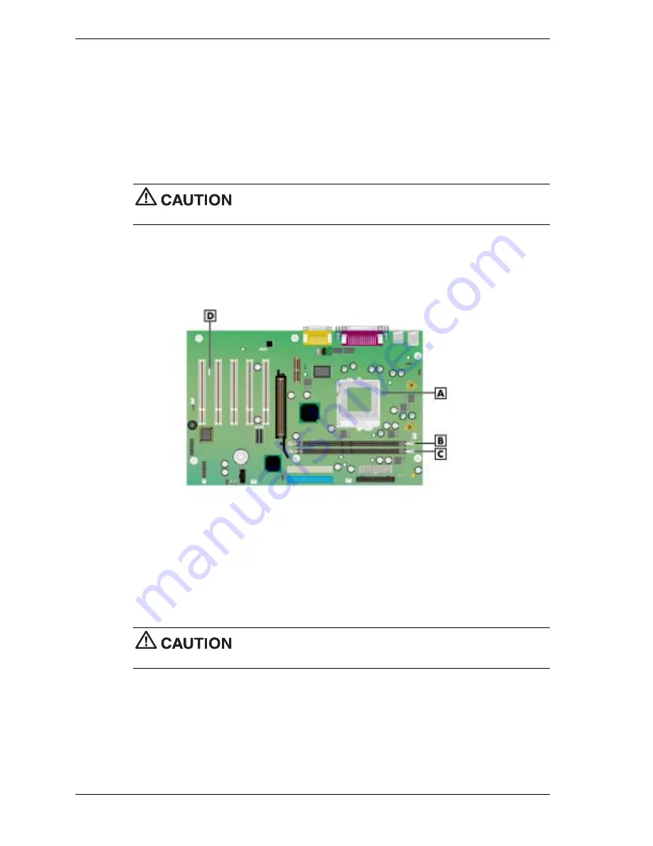
Locate the RIMM memory sockets on the system board (see the following figure).
Locating the RIMM and Processor Sockets
A – Processor Socket
C – RIMM 2 Socket
B – RIMM 1 Socket
D – Wake-On LAN (WOL) Connector
3.
Eject a RIMM module or continuity module by pressing the plastic clips at the outer edges
of the socket away from the module (see the following figures).
For module identification, note that the RIMM module is taller than the continuity module
and has a cover over the memory on the module. Also note that the continuity module has
no memory installed on it.
If the system was just turned off, the RIMM module might be hot to the
touch. Use caution in removing the module to avoid a burn.
4.
Grasp the center of the module and pull it straight up and out of the socket. Store the
module in an anti-static bag.
5.
As required, install a replacement RIMM or continuity module (see “Installing a RIMM or
Continuity Module” in the next section).
Summary of Contents for PowerMate CT
Page 13: ...1 System Overview Configurations Features Components...
Page 118: ...6 Preventive Maintenance System Cleaning Keyboard Cleaning Mouse Cleaning...
Page 121: ...7 Troubleshooting Checklist Diagnostics...
Page 130: ...8 NECC Information Services Service Telephone Numbers Technical Support...


