background image

13

Wide Screen Operation


(manual)

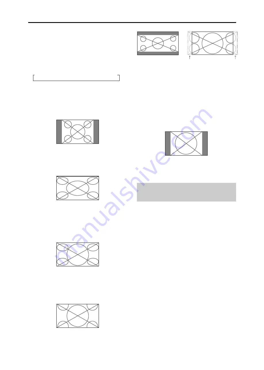
With this function, you can select one of six screen sizes.

When viewing videos or digital video discs

1. Press the WIDE button on the remote control.
2.

Within 3 seconds ...

Press the WIDE button again.
The screen size switches as follows:


NORMAL


FULL


STADIUM


ZOOM


2.35:1


14:9

When a 720P or 1080I signal is input:

FULL


2.35:1

When displaying enhanced split screen:

NORMAL


FULL

NORMAL size screen (4:3)

The normal size screen is displayed.
* The picture has the same size as video pictures with a 4 : 3

aspect ratio.

FULL size screen

The image is expanded in the horizontal direction.
* Images compressed in the horizontal direction (“squeezed

images”) are expanded in the horizontal direction and
displayed on the entire screen with correct linearity.
(Normal images are expanded in the horizontal direction.)

STADIUM size screen

The picture is expanded in the horizontal and vertical
directions at different ratios.
* Use this for watching normal video programs (4:3) with a

wide screen.

ZOOM size screen

The picture is expanded in the horizontal and vertical
direction, maintaining the original proportions.
* Use this for theater size (wide) movies, etc.

2.35:1 size screen

The squeezed film image is expanded to fulfill the entire
screen at a ratio of 2.35:1. Black bands do not appear at
the top and bottom but information is lost on the left and
right margins.
• This feature is available when the input signal is video,

component (480I, 480P, 576I, 576P, 720P, 1080I) or RGB
(525P or 625P signal from a scan converter).

* If black bands appear on the top and bottom in the full size

screen, select the 2.35:1 size screen to avoid phosphor burn-
in.

14:9 size screen

The image is displayed at a 14:9 aspect ratio.
* This feature is available when the input signal is video,

component (480I, 480P, 576I, 576P) or RGB (525P or 625P
signal from a scan converter).

Note:

Do not allow the displayed in 4:3 mode for an extended
period. This can cause a phosphor burn-in.

Information is lost on both sides.

Original image

WIDE Operations

Summary of Contents for PlasmaSync SERIES

Page 1: ...PlasmaSync Plasma Monitor NEC Solutions America Inc Operation Manual Enhanced split screen Model For the specifications of your plasma monitor refer to Model Information ...

Page 2: ...cord during electrical storms or if the unit will not be used over a long period 6 Do not open the cabinet which has potentially dangerous high voltage components inside If the unit is damaged in this way the warranty will be void Moreover there is a serious risk of electric shock 7 Do not attempt to service or repair the unit The manufacturer is not liable for any bodily harm or damage caused if ...

Page 3: ...ILISER LA FICHE POLARISEE AVEC UN PROLONGATEUR OU UNE AUTRE PRISE DE COURANT SAUF SI CES LAMES PEUVENT ETRE INSEREES A FOND NE PAS OUVRIR LE COFFRET DES COMPOSANTS HAUTETENSION SETROUVENT A L INTERIEUR LAISSER A UN PERSONNEL QUALIFIE LE SOIN DE REPARER CET APPAREIL Mises en garde et précautions de sécurité Ce moniteur à plasma a été conçu et fabriqué pour une utilisation fiable et durable Il ne né...

Page 4: ...toyagedecessurfaces 2 Nettoyer les prises d aération du plasma en procédant à l aide d une brosse à poils doux fixée à un aspirateur 3 Pour garantir la bonne ventilation du moniteur nettoyer les prises d air tous les mois Un nettoyage plus fréquent peut s avérer nécessaire selon les conditions environnantes dans lesquelles le moniteur à plasma est utilisé Pour éviter les risques de brûlage du lumi...

Page 5: ...nsmitted to RGB1 terminal 23 Setting a computer image to the correct RGB select screen 23 Setting high definition images to the suitable screen size 24 Setting the Input Skip 24 Resetting to the default values 24 Option2 Settings Menu 25 Setting the power management for computer images 25 POWER STANDBY indicator 25 Setting the picture to suit the movie 25 Reducing burn in of the screen 25 Setting ...

Page 6: ... the equipment or injury to the installer Product warranty does not cover damage caused by improper installation Use only the mounting kit or stand provided by manufacturer and listed under Options Drawing B Drawing A When installing or carrying use the handles attached to the upper back of the display How to use the safety metal fittings and the screws for safety metal fittings These are fittings...

Page 7: ...ximaly 4 screen is rough standard with lower than 1024 768 60Hz signal A distribution amplifier is particularly recommended when using 9 screen and over video wall From the second monitor onward connections require a BNC RCA conversion cable or connector a mini D Sub 15 pin cable BNC 5 cable or a conversion connector Creating a video wall With built in matrix display capability you can create a 4 ...

Page 8: ...ntrol within a distance of about 7 m 23ft from the front of the monitor s remote control sensor andathorizontalandverticalanglesofuptoapproximately 30 The remote control operation may not function if the monitor s remote control sensor is exposed to direct sunlight or strong artificial light or if there is an obstacle between the sensor and the remote control Handling the remote control Do not dro...

Page 9: ...in the On Screen Menu OSM mode Front View MENU ENTER INPUTSELECT DOWN UP LEFT RIGHT EXIT VOLUME MENU ENTER INPUTSELECT DOWN UP LEFT RIGHT EXIT VOLUME 4 5 6 7 1 3 2 t LEFT and RIGHT Enlarges or reduces the image Functions as the CURSOR buttons in the On Screen Menu OSM mode y VOLUME DOWN and UP Adjusts the volume Functions as the CURSOR buttons in the On Screen Menu OSM mode u MENU ENTER Sets the O...

Page 10: ...r Discs etc here This input can be set for use with an RGB or component source see page 23 G RGB1 mini D Sub 15pin Connect an analog RGB signal from a computer etc here This input can be used for Input or Output see page 7 H RGB3 DVI 24pin Connect a digital signal TMDS from a source with a DVI output This input can be set for use with an RGB PC3 see page 28 I EXTERNAL CONTROL This terminal is used...

Page 11: ...e settings on the screen 4 OFF TIMER Activates the off timer for the unit 5 SIDE BY SIDE Press this button to show a couple of pictures in the side by side mode 6 PICTURE IN PICTURE Press this button to show a couple of pictures in the picture in picture mode 7 SINGLE Cancels the split screen mode 8 SELECT FRREZE Press this button to select the active picture in a split screen mode When the PIC FR...

Page 12: ...magnifying glass A press of the ZOOM button will reduce the picture and return it to its original size To change the picture position Select the position with the buttons 2 Press the POINTER button to delete the pointer AUTO ADJUST To adjust the size or quality of the picture automatically Press the AUTO ADJUST button Information AUTO ADJUST ON setting When RGB still picture input is selected Fine...

Page 13: ...irections at different ratios Use this for watching normal video programs 4 3 with a wide screen ZOOM size screen The picture is expanded in the horizontal and vertical direction maintaining the original proportions Use this for theater size wide movies etc 2 35 1 size screen The squeezed film image is expanded to fulfill the entire screen at a ratio of 2 35 1 Black bands do not appear at the top ...

Page 14: ...A are registered trademarks of IBM Inc of the United States Note Do not allow the displayed in 4 3 mode for an extended period This can cause a phosphor burn in Wide Screen Operation with Computer Signals Switch to the wide screen mode to expand the 4 3 image to fill the entire screen 1 Press the WIDE button on the remote control 2 Within 3 seconds Press the WIDE button again The screen size switc...

Page 15: ...pending on the combination of input signals In the table below means Yes means No Split screen operations may not function depending on the type of the RGB signals VIDEO1 VIDEO2 VIDEO3 HD DVD1 HD DVD2 RGB2 RGB PC1 RGB3 VIDEO1 VIDEO2 VIDEO3 HD DVD1 HD DVD2 RGB2 RGB PC1 RGB3 Pictures displayed on the left sub screen Select2 Pictures displayed on the right main screen Select1 button VIDEO1 RGB PC2 A ...

Page 16: ...an also be used to change the selection Zooming up pictures 1 Press the SELECT FREEZE button to make the desired picture active 2 Use the POINTER button and the ZOOM button to enlage the picture For details see DIGITAL ZOOM on page 12 Adjusting the OSM controls 1 Press the SELECT FREEZE button to make the desired picture active 2 Press the MENU ENTER button to display the MAIN MENU 3 Adjust the se...

Page 17: ...utton on the remote control to select a sub menu or item PICTURE 1 2 EXIT CONTRAST BRIGHTNESS SHARPNESS COLOR TINT PICTURE MODE NR NEXT PAGE NORMAL OFF SEL RETURN ADJ 4 Adjust the level or change the setting of the selected item by using the cursor buttons on the remote control 5 The adjustments or the settings that are stored in memory The change is stored until you change it again 6 Repeat steps...

Page 18: ...INPUT1 VIDEO 1 3 HD DVD 1 2 RGB 1 3 YES 22 AUDIO INPUT2 VIDEO 1 3 HD DVD 1 2 RGB 1 3 YES 22 AUDIO INPUT3 VIDEO 1 3 HD DVD 1 2 RGB 1 3 YES 22 Main menu Sub menu Sub menu 2 Sub menu 3 Sub menu 4 RESET REFERENCE IMAGE ADJUST ASPECT MODE NORMAL FULL STADIUM ZOOM 2 35 1 14 9 22 V POSITION 64 64 YES 22 H POSITION 128 127 YES 22 V HEIGHT 0 64 YES 22 H WIDTH 0 64 YES 22 AUTO PICTURE OFF ON 2 NO 22 FINE PI...

Page 19: ...N YES 31 LOOP OUT OFF ON YES 31 ID NUMBER ALL 1 256 YES 31 VIDEO WALL DIVIDER OFF 1 4 9 YES 32 POSITION No 1 No 4 No 7 No 15 No 16 No 31 No 32 No 56 32 DISP MODE SPLIT BLANK YES 32 AUTO ID OFF ON YES 32 IMAGE ADJUST ASPECT MODE NORMAL FULL STADIUM ZOOM 2 35 1 14 9 33 V POSITION 64 64 YES 33 H POSITION 128 127 YES 33 V HEIGHT 0 64 YES 33 H WIDTH 0 64 YES 33 AUTO PICTURE OFF ON 2 NO 33 FINE PICTURE ...

Page 20: ...ETURN ADJ PICTURE MODE THEAT 1 Information Types of picture modes THEAT 1 2 Set this mode when watching video in a dark room This mode provides darker finer pictures like the screen in movie theaters For a darker image select THEAT 2 NORMAL Setthismodewhenwatchingvideoinabright room This mode provides dynamic pictures with distinct differences between light and dark sections BRIGHT This mode provi...

Page 21: ...es darker as the number increases in the sequence of 1 2 3 4 Making the Low Tone adjustments This feature allows more detailed tone to be reproduced especially in the dark area Example Setting 2 Set ADVANCED OSM to ON in the MAIN MENU 1 2 then perform the following operations On LOW TONE of PICTURE menu select 2 PICTURE 2 2 EXIT PREVIOUS PAGE COLOR TEMP GAMMA LOW TONE COLOR TUNE MID 2 2 SEL RETURN...

Page 22: ...de switches as follows each time the or button is pressed NORMAL FULL The mode can also be switched by pressing the WIDE button on the remote control The settings on the IMAGEADJUST menu are not preset at the factory IMAGE ADJUST EXIT ASPECT MODE V POSITION H POSITION V HEIGHT H WIDTH AUTO PICTURE FINE PICTURE PICTURE ADJ NORMAL OFF SEL RETURN ADJ V POSITION 64 Information When AUTO PICTURE is OFF...

Page 23: ...rmation BNC INPUT Settings RGB Use the 5BNC terminals for RGB input COMP Use the 3BNC terminals for component input OPTION1 1 4 EXIT OSM BNC INPUT D SUB INPUT RGB SELECT HD SELECT INPUT SKIP ALL RESET NEXT PAGE RGB RGB AUTO 1080B OFF OFF SEL RETURN MENU ENTER OK OPTION1 EXIT OSM BNC INPUT D SUB INPUT RGB SELECT HD SELECT INPUT SKIP ALL RESET RGB RGB AUTO 1080B OFF OFF 1024 768 SEL RETURN MENU ENTE...

Page 24: ... of the signal scan and display all signals ON If no input signal is present skip that signal SETTING NOW will appear during the input search WIDE1 When an 852 dot 480 line signal with a horizontal frequency of 31 7kHz is input the image may be compressed horizontally To prevent this set RGB SELECT to WIDE1 WIDE2 When an 848 dot 480 line signal with a horizontal frequency of 31 0 kHz is input the ...

Page 25: ...gement operating status Not activated Activated Description Horizontal and vertical synchronizing signals are present from the computer Horizontal and or vertical synchronizing signals are not sent from the computer Setting the picture to suit the movie The film image is automatically discriminated and projected in an image mode suited to the picture NTSC PAL PAL60 480I 60Hz 525I 60Hz 576I 50Hz 62...

Page 26: ...erval of 1 5 minutes 1 horizontal dot or 1 vertical line per interval INVERSE Use this to set the inverse mode or to display a white screen Example Setting INVERSE to WHITE On INVERSE of LONG LIFE menu select WHITE LONG LIFE EXIT PLE ORBITER INVERSE SCREEN WIPER SOFT FOCUS AUTO OFF WHITE OFF OFF SEL RETURN ADJ Information 䡵 INVERSE Settings ON The picture is displayed alternately between positive ...

Page 27: ...ot be set when the WORKING TIME is ON THE WORKINGTIME and WAITINGTIME can be set for up to 12 hours and 45 minutes in units of 3 minutes 䡵 To select ON for the WORKING TIME Set the hours of the working time to 0H and the minutes to 0M ON will be displayed SOFT FOCUS Reduces edges and softens the image Example Setting SOFT FOCUS to 2 On SOFT FOCUS of LONG LIFE menu select 2 LONG LIFE EXIT PLE ORBIT...

Page 28: ...TURN ADJ Setting CloseCaption Choose the closed caption mode that allows text to be superimposed on display Example Setting CLOSECAPTION to CC2 Set ADVANCED OSM to ON in the main menu 1 2 then perform the following operations On CLOSECAPTION of OPTION2 menu select CC2 OPTION2 2 4 EXIT PREVIOUS PAGE PWR MGT CINEMA MODE LONG LIFE GRAY LEVEL S1 S2 PICTURE SIZE DVI SETUP CLOSECAPTION CAPTION CONT NEXT...

Page 29: ... On PROGRAM of TIMER menu select ON then press the MENU ENTER button The PROGRAM TIMER screen appears Adjust the items Each mode switches each time the ZOOM Ⳮ ⳮ button is pressed PROGRAM TIMER EXIT DATE MON SEL RETURN ADJ ZOOM ON 08 30 OFF 10 30 INPUT RGB2 FUNCTION INVERSE Information 䡵 PROGRAM TIMER settings DATE Set the day of the week e g Sunday ON hour minutes Set the time at which the power w...

Page 30: ...MAIN or SUB for PICTURE IN PICTURE BTM LFT TOP LFT and LEFT or RIGHT for S BY S1 3 Only one signal is selected for SINGLE The two repeat timers run consecutively i e Timer1 Timer2 Timer1 Timer2 When both PROGRAMTIMER and MULTI REPEAT TIMERareset priorityisgiventoPROGRAMTIMER PROGRAM TIMER MULTI SCREEN SETTING EXIT MULTI MODE SIDE BY SIDE1 INPUT MODE LEFT RIGHT SEL RETURN ADJ RGB PC1 VIDEO1 Setting...

Page 31: ... the ID number for the remote control Example Setting 2 Press the ID SELECT button on the remote control The ID SELECT screen appears On ID NUMBER of ID SELECT menu select 2 ID SELECT POSITION 1 EXIT 2 RETURN ADJ ID NUMBER To reset back to ALL Press the CLEAR SEAMLESS SW button Video Wall setting When creating a video wall use a distribution amplifier any commercially available distribution amplif...

Page 32: ...play 1 Display 2 Display 4 Display 3 OFF Disables Auto ID function DISP MODE Select the screen mode from between two options Splitting Blanking Example Setting BLANK On DISP MODE of VIDEO WALL menu select BLANK VIDEO WALL EXIT DIVIDER POSITION DISP MODE AUTO ID IMAGE ADJUST P ON DELAY PLE LINK REPEAT TIMER 1 BLANK OFF OFF OFF OFF SEL RETURN ADJ Information 䡵 DISP MODE settings SPLIT Combines enlar...

Page 33: ...cted Example Adjusting the vertical position On VIDEOWALL menu select IMAGEADJUST then press the MENU ENTER button The IMAGE ADJUST screen appears On V POSITION of IMAGEADJUST menu adjust the position IMAGE ADJUST EXIT ASPECT MODE V POSITION H POSITION V HEIGHT H WIDTH AUTO PICTURE FINE PICTURE PICTURE ADJ NORMAL OFF SEL RETURN ADJ V POSITION 64 Information 䡵 IMAGE ADJUST settings These are the sa...

Page 34: ...VANCED OSM to ON in the main menu 1 2 then perform the following operations On ZOOM NAV of OPTION4 menu select S BY S OPTION4 4 4 EXIT PREVIOUS PAGE SUB P DETECT ZOOM NAV PIC FREEZE SEAMLESS SW SELECT1 SELECT2 AUTO S BY S S BY S OFF SEL RETURN ADJ Information 䡵 ZOOM NAV Function This feature is available only for RGB1 or RGB2 input signals Thisfeaturedoesnotfunctionduringmultiscreenmode This featu...

Page 35: ...ntire image on the sub screen S BY S Will show the entire image on the sub screen of side by side mode BTM LFT TOP LFT Will show the entire image on the sub screen of picture in picture mode Displaying still images in the sub screen This feature enables display in the sub screen of still images captured by pressing the SELECT FREEZE button Example Setting PIC FREEZE to BTM LFT Set ADVANCED OSM to ...

Page 36: ...etc On MAIN MENU select SOURCE INFORMATION then press the MENU ENTER button The SOURCE INFORMATION is displayed SOURCE INFORMATION EXIT H FREQ V FREQ H POLARITY V POLARITY MEMORY RESOLUTION 48 4KHZ 60 0HZ NEG NEG 24 1024 768 RETURN PC MEMORY will be displayed Others MODE will be displayed Advanced OSM Settings Menu Setting the menu mode This allows you to access full menu items When P ON DELAY or ...

Page 37: ...1H 01H 01H 82H OFF DFH 80H 60H C1H 01H 02H 83H Note Contact your local dealer for a full list of the External Control Codes if needed 1 5 9 6 2 3 4 7 8 Communication Parameters 1 Communication system Asynchronous 2 Interface RS 232C 3 Baud rate 9600 bps 4 Data length 8 bits 5 Parity Odd 6 Stop bit 1 bit 7 Communication code Hex Pin Name No Connection RXD Receive data TXD Transmit data DTR DTE side...

Page 38: ...or or colors are weak Nothing appears on screen Part of picture is cut off or picture is not centered Image is too large or too small Picture is unstable POWER STANDBY indicator is lighted in red POWER STANDBY indicator is blinking in red POWER STANDBY indicator is blinking in green and red or green Checks Are the image and sound normal Is a connected component set directly in front or at the side...

Page 39: ...tial technical adjustments set up including adjustment of user controls These costs are the responsibility of the NEC Solutions dealer from whom the product was purchased 3 Shipping charges HOW YOU CAN GET WARRANTY SERVICE 1 To obtain service on your product consult the dealer from whom you purchased the product 2 Whenever warranty service is required the original dated invoice or a copy must be p...

Page 40: ...Printed on recycled paper Printed in Japan 7S801381 NEC Solutions America Inc 1250 N Arlington Heights Road Suite 400 Itasca Illinois 60143 1248 ...

Reviews: