background image

25

SCREEN WIPER

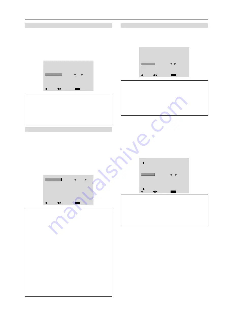
When this is set to ON, a white vertical bar moves
repeatedly from the left and of the screen to the right end
at a constant speed.

Example: Setting “SCREEN WIPER” to “ON”

On  “SCREEN WIPER” of “LONG LIFE” menu, select
“ON”.

LONG LIFE

EXIT

PLE

ORBITER

INVERSE

SCREEN WIPER

SOFT FOCUS

:     AUTO

:     OFF

:     OFF

:     

ON

:     OFF

SEL.

RETURN

ADJ.

Information

 SCREEN WIPER

ON:

 The white vertical bar appears.

You can set the time by pressing the MENU/ENTER
button while “ON” is set.

OFF:

 Screen wiper mode does not function.

Setting the time for SCREEN WIPER

Set a time duration and the speed.

Example: Setting so that the SCREEN WIPER mode
starts in 30 minutes and proceeds for one and a half
hours.

On  “SCREEN WIPER” of “LONG LIFE” menu, select
“ON”, then press the MENU/ENTER button.
THE “SCREEN WIPER” screen appears.
Adjust the times and speed.

SCREEN WIPER

EXIT

WORKING TIME

WAITING TIME

SPEED

:     

01H30M

:     00H30M

:     3

SEL.

RETURN

ADJ.

Information

 Setting the time

WORKING TIME:

 Set the time duration for “SCREEN

WIPER”.
When the WORKING TIME is set to “ON” the mode
will stay on.

WAITING TIME:

 Set the standby time until the

“SCREEN WIPER” mode starts.

SPEED:

 Set the moving speed for the  “SCREEN

WIPER”. The speed decreases as the number increases.

* The  “WAITING TIME” can not be set when the

“WORKING TIME” is ON.

* THE “WORKING TIME” and “WAITING TIME” can

be set for up to 12 hours and 45 minutes in units of 3
minutes.

 To select “ON” for the “WORKING TIME”...

Set the hours of the working time to 0H and the minutes
to 0M. “ON” will be displayed.

SOFT FOCUS

Reduces edges and softens the image.

Example: Setting “SOFT FOCUS” to “2”

On “SOFT FOCUS” of “LONG LIFE” menu, select “2”.

LONG LIFE

EXIT

PLE

ORBITER

INVERSE

SCREEN WIPER

SOFT FOCUS

:     AUTO

:     OFF

:     OFF

:     OFF

:     

2

SEL.

RETURN

ADJ.

Information

 SOFT FOCUS settings

OFF:

 Turns the SOFT FOCUS function off.

1, 2, 3, 4:

 Activates the SOFT FOCUS setting. The

higher numbers create a softer image.
“SHARPNESS” can not be adjusted  in the “PICTURE”
menu.

Setting the gray level for the sides of the screen

Use this procedure to set the gray level for the parts on the
screen on which nothing is displayed when the screen is
set to the 4:3 size.

Example: Setting “GRAY LEVEL” to “5”

Set “ADVANCED OSM” to “ON” in the main menu (1/
2), then perform the following operations.

On “GRAY LEVEL” of “OPTION2” menu, select “5”.

OPTION2

2 / 3

EXIT

        PREVIOUS PAGE

PWR. MGT.

CINEMA MODE

LONG LIFE

GRAY LEVEL

S1/S2

DVI SET UP

CLOSECAPTION

CAPTION CONT

        NEXT PAGE

:     OFF

:     ON

:     

5

:     OFF

:     OFF

:     LOW

SEL.

RETURN

ADJ.

Information

 GRAY LEVEL settings

This adjusts the brightness of the black (the gray level)
for the sides of the screen.
The standard is 0 (black). The level can be adjusted
from 0 to 15. The factory setting is 3 (dark gray).

Summary of Contents for PlasmaSync 42XM3

Page 1: ...PlasmaSync Plasma Monitor NEC Solutions America Inc Operation Manual For the specifications of your plasma monitor refer to Model Information ...

Page 2: ... Avoid damage to the power cord and do not attempt to modify the power cord 5 Unplug the power cord during electrical storms or if the unit will not be used over a long period 6 Do not open the cabinet which has potentially dangerous high voltage components inside If the unit is damaged in this way the warranty will be void Moreover there is a serious risk of electric shock 7 Do not attempt to ser...

Page 3: ...ryorpastelcolorwhenever possible Avoid displaying images with few colors and distinct sharply defined borders between colors Note Burn in is not covered by the warranty Contact your dealer for other recommended procedures that will best suit your particular application needs Mises en garde et précautions de sécurité Ce moniteur à plasma a été conçu et fabriqué pour une utilisation fiable et durabl...

Page 4: ...ttoyer les prises d aération du plasma en procédant à l aide d une brosse à poils doux fixée à un aspirateur 3 Pour garantir la bonne ventilation du moniteur nettoyer les prises d air tous les mois Un nettoyage plus fréquent peut s avérer nécessaire selon les conditions environnantes dans lesquelles le moniteur à plasma est utilisé Pour éviter les risques de brûlage du luminophore les mesures suiv...

Page 5: ...ture 18 Setting the color temperature 18 Adjusting the color to the desired level 19 Changing the Gamma Curve 19 Making the Low Tone adjustments 19 Adjusting the colors 19 Audio Settings Menu 20 Adjusting the treble bass and left right balance and audio input select 20 Setting the allocation of the audio connectors 20 Image Adjust Settings Menu 20 Adjusting the Position Size Fine Picture Picture A...

Page 6: ...Failure to follow correct mounting procedures could result in damage to the equipment or injury to the installer Product warranty does not cover damage caused by improper installation Use only the mounting kit or stand provided by manufacturer and listed under Options Drawing B Drawing A How to use the safety metal fittings and the screws for safety metal fittings These are fittings for fastening ...

Page 7: ...ximaly 4 screen is rough standard with lower than 1024 768 60Hz signal A distribution amplifier is particularly recommended when using 9 screen and over video wall From the second monitor onward connections require a BNC RCA conversion cable or connector a mini D Sub 15 pin cable BNC 5 cable or a conversion connector Creating a video wall With built in matrix display capability you can create a 4 ...

Page 8: ...hen the cable is connected the mode automatically switches to wired remote control When the wired remote control mode is used the remote control can be operated even if no batteries are loaded External Control IN OUT REMOTE Remote Control Cable To Remote Jack Operating Range Use the remote control within a distance of about 7 m 23ft from the front of the monitor s remote control sensor andathorizo...

Page 9: ...in the On Screen Menu OSM mode Front View MENU ENTER INPUTSELECT DOWN UP LEFT RIGHT EXIT VOLUME MENU ENTER INPUTSELECT DOWN UP LEFT RIGHT EXIT VOLUME 4 5 6 7 1 3 2 t LEFT and RIGHT Enlarges or reduces the image Functions as the CURSOR buttons in the On Screen Menu OSM mode y VOLUME DOWN and UP Adjusts the volume Functions as the CURSOR buttons in the On Screen Menu OSM mode u MENU ENTER Sets the O...

Page 10: ... etc here This input can be set for use with an RGB or component source see page 21 G RGB1 mini D Sub 15pin Connect an analog RGB signal from a computer etc here This input can be used for Input or Output see page 7 H RGB3 DVI 24pin Connect a digital signal TMDS from a source with a DVI output This input can be set for use with an RGB PC3 see page 26 I EXTERNAL CONTROL This terminal is used when o...

Page 11: ...nu i POINTER Press this button to display the pointer o ZOOM Enlarges or reduces the image 0 VOLUME Adjusts the audio volume 1 MUTE Mutes the audio 2 WIDE Automatically detects the signal and sets the aspect ratio Wide button is not active for all signals 3 DISPLAY Displays the source settings on the screen 4 OFF TIMER Activates the off timer for the unit 5 MULTI Not functional for the models cove...

Page 12: ...ng glass A press of the ZOOM button will reduce the picture and return it to its original size To change the picture position Select the position with the buttons 2 Press the POINTER button to delete the pointer AUTO ADJUST To adjust the size or quality of the picture automatically Press the AUTO ADJUST button Information AUTO ADJUST ON setting When RGB still picture input is selected Fine Picture...

Page 13: ...tios Use this for watching normal video programs 4 3 with a wide screen ZOOM size screen The picture is expanded in the horizontal and vertical direction maintaining the original proportions Use this for theater size wide movies etc 2 35 1 size screen The squeezed film image is expanded to fulfill the entire screen at a ratio of 2 35 1 Black bands do not appear at the top and bottom but informatio...

Page 14: ...he normal computer image FULL size screen The image is expanded in the horizontal direction ZOOM size screen When wide signals are input FULL size screen Information Supported resolution See page 7 of Model Information for details on the display output of the various VESA signal standards supported by the monitor When 852 848 dot 480 line wide VGA signals with a vertical frequency of 60 Hz and hor...

Page 15: ... button on the remote control to select a sub menu or item PICTURE 1 2 EXIT CONTRAST BRIGHTNESS SHARPNESS COLOR TINT PICTURE MODE NR NEXT PAGE NORMAL OFF SEL RETURN ADJ 4 Adjust the level or change the setting of the selected item by using the cursor buttons on the remote control 5 The adjustments or the settings that are stored in memory The change is stored until you change it again 6 Repeat ste...

Page 16: ...INPUT1 VIDEO 1 3 HD DVD 1 2 RGB 1 3 YES 20 AUDIO INPUT2 VIDEO 1 3 HD DVD 1 2 RGB 1 3 YES 20 AUDIO INPUT3 VIDEO 1 3 HD DVD 1 2 RGB 1 3 YES 20 Main menu Sub menu Sub menu 2 Sub menu 3 Sub menu 4 RESET REFERENCE IMAGE ADJUST ASPECT MODE NORMAL FULL STADIUM ZOOM 2 35 1 14 9 20 V POSITION 64 64 YES 20 H POSITION 128 127 YES 20 V HEIGHT 0 64 YES 20 H WIDTH 0 64 YES 20 AUTO PICTURE OFF ON 2 NO 20 FINE PI...

Page 17: ...N MODE LAST VIDEO 1 3 HD DVD 1 2 RGB 1 3 YES 28 CONTROL LOCK OFF ON YES 28 IR REMOTE OFF ON YES 28 LOOP OUT OFF ON YES 28 ID NUMBER ALL 1 256 YES 29 VIDEO WALL DIVIDER OFF 1 4 9 16 25 YES 29 POSITION No 1 No 4 No 7 No 15 No 16 No 31 No 32 No 56 29 DISP MODE SPLIT BLANK YES 30 AUTO ID OFF ON YES 30 IMAGE ADJUST ASPECT MODE NORMAL FULL STADIUM ZOOM 2 35 1 14 9 30 V POSITION 64 64 YES 30 H POSITION 1...

Page 18: ...URN ADJ CONTRAST 52 Note If CAN NOT ADJUST appears When trying to enter the PICTURE submenu make sure PICTURE MODE is not set to DEFAULT Information Picture adjustment screen CONTRAST Changes the picture s white level BRIGHTNESS Changes the picture s black level SHARPNESS Changes the picture s sharpness Adjusts picture detail of VIDEO display COLOR Changes the color density TINT Changes the pictur...

Page 19: ...es darker as the number increases in the sequence of 1 2 3 4 Making the Low Tone adjustments This feature allows more detailed tone to be reproduced especially in the dark area Example Setting 2 Set ADVANCED OSM to ON in the MAIN MENU 1 2 then perform the following operations On LOW TONE of PICTURE menu select 2 PICTURE 2 2 EXIT PREVIOUS PAGE COLOR TEMP GAMMA LOW TONE COLOR TUNE MID 2 2 SEL RETURN...

Page 20: ...switches as follows each time the 䊴 or 䊳 button is pressed NORMAL FULL The mode can also be switched by pressing the WIDE button on the remote control The settings on the IMAGEADJUST menu are not preset at the factory IMAGE ADJUST EXIT ASPECT MODE V POSITION H POSITION V HEIGHT H WIDTH AUTO PICTURE FINE PICTURE PICTURE ADJ NORMAL OFF SEL RETURN ADJ V POSITION 64 Information 䡵 When AUTO PICTURE is ...

Page 21: ...nformation 䡵 BNC INPUT Settings RGB Use the 5BNC terminals for RGB input COMP Use the 3BNC terminals for component input Checking the signal being transmitted to RGB1 terminal Use this to confirm the signal being transmitted to the RGB1 terminal It is set to RGB and can not be adjusted OPTION1 1 3 OSM BNC INPUT D SUB INPUT RGB SELECT HD SELECT INPUT SKIP ALL RESET NEXT PAGE CAN NOT ADJUST RGB RGB ...

Page 22: ...ce of the signal scan and display all signals ON If no input signal is present skip that signal SETTING NOW will appear during the input search Resetting to the default values Use these operations to restore all the settings PICTURE AUDIO IMAGE ADJUST OPTION1 3 etc to the factory default values Refer to page 16 for items to be reset On ALL RESET of OPTION1 menu select ON then press the MENU ENTER ...

Page 23: ...gement operating status Not activated Activated Description Horizontal and vertical synchronizing signals are present from the computer Horizontal and or vertical synchronizing signals are not sent from the computer Setting the picture to suit the movie The film image is automatically discriminated and projected in an image mode suited to the picture NTSC PAL PAL60 480I 60Hz 525I 60Hz 576I 50Hz 62...

Page 24: ...erval of 1 5 minutes 1 horizontal dot or 1 vertical line per interval INVERSE Use this to set the inverse mode or to display a white screen Example Setting INVERSE to WHITE On INVERSE of LONG LIFE menu select WHITE LONG LIFE EXIT PLE ORBITER INVERSE SCREEN WIPER SOFT FOCUS AUTO OFF WHITE OFF OFF SEL RETURN ADJ Information 䡵 INVERSE Settings ON The picture is displayed alternately between positive ...

Page 25: ...E can not be set when the WORKING TIME is ON THE WORKINGTIME and WAITINGTIME can be set for up to 12 hours and 45 minutes in units of 3 minutes 䡵 To select ON for the WORKING TIME Set the hours of the working time to 0H and the minutes to 0M ON will be displayed SOFT FOCUS Reduces edges and softens the image Example Setting SOFT FOCUS to 2 On SOFT FOCUS of LONG LIFE menu select 2 LONG LIFE EXIT PL...

Page 26: ...LEVEL settings LOW When connected to the PC signal HIGH When connected to the SET TOP BOX DVD etc Change HIGH into LOW if the black level appears gray Setting CloseCaption Choose the closed caption mode that allows text to be superimposed on display Example Setting CLOSECAPTION to CC2 Set ADVANCED OSM to ON in the main menu 1 2 then perform the following operations On CLOSECAPTION of OPTION2 menu ...

Page 27: ...at 8 30 A M Monday displaying RGB2 source and switched off at 10 30 A M On PROGRAM of TIMER menu select ON then press the MENU ENTER button The PROGRAM TIMER screen appears Adjust the items Each mode switches each time the ZOOM Ⳮ ⳮ button is pressed PROGRAM TIMER EXIT DATE MON SEL RETURN ADJ ZOOM ON 08 30 OFF 10 30 INPUT RGB2 FUNCTION INVERSE Information 䡵 PROGRAM TIMER settings DATE Set the day o...

Page 28: ...becomes effective when the on screen menu goes out Enabling disabling remote control wireless transmission This function enables disables remote control wireless transmission Example Setting OFF Set ADVANCED OSM to ON in the main menu 1 2 then perform the following operations On IRREMOTE of OPTION3 menu select OFF then press the MENU ENTER button OPTION3 3 3 EXIT PREVIOUS PAGE TIMER PWR ON MODE CO...

Page 29: ...DEO WALL screen appears VIDEO WALL EXIT DIVIDER POSITION DISP MODE AUTO ID IMAGE ADJUST P ON DELAY PLE LINK REPEAT TIMER 1 SPLIT OFF OFF OFF OFF SEL RETURN ADJ Note A contingency method of shutting off the electric power should be used in cases of emergency during video wall setup DIVIDER Set the 4 25 video wall Example Setting 4 On DIVIDER of VIDEO WALL menu select 4 VIDEO WALL EXIT DIVIDER POSIT...

Page 30: ...n mode from between two options Splitting Blanking Example Setting BLANK On DISP MODE of VIDEO WALL menu select BLANK VIDEO WALL EXIT DIVIDER POSITION DISP MODE AUTO ID IMAGE ADJUST P ON DELAY PLE LINK REPEAT TIMER 1 BLANK OFF OFF OFF OFF SEL RETURN ADJ Information 䡵 DISP MODE settings SPLIT Combines enlarged screens and creates multiple screens BLANK Corrects misalignment of combined screen porti...

Page 31: ...rs Each timer can use the DIVIDER SOURCE and WORK TIME functions Turn on the AUTO ID and set the DIVIDER at 1 4 or 9 before the following operations Example TIMER1 VIDEO1 will be displayed for 3 minutes TIMER2 RGB1 will be displayed for 6 minutes in a 2 2 video wall On REPEAT TIMER of VIDEO WALL menu select ON then press the MENU ENTER button The REPEAT TIMER screen appears Adjust the items REPEAT...

Page 32: ...standard format used mainly in Brazil PAL N This is the standard format used mainly in Argentina Source Information Menu Checking the frequencies polarities of input signals and resolution Use this function to check the frequencies and polarities of the signals currently being input from a computer etc On MAIN MENU select SOURCE INFORMATION then press the MENU ENTER button The SOURCE INFORMATION i...

Page 33: ... 09H 1AH 2 35 1 DFH 80H 60H 51H 01H 0AH 1BH Auto Picture ON DFH 80H 60H 7FH 03H 03H 09H 00H 4DH OFF DFH 80H 60H 7FH 03H 03H 09H 01H 4EH Cinema Mode ON DFH 80H 60H C1H 01H 01H 82H OFF DFH 80H 60H C1H 01H 02H 83H Note Contact your local dealer for a full list of the External Control Codes if needed Display External equipment e g Personal computer 5 4 3 2 1 15 14 13 12 11 10 9 8 7 6 RGB 1 mini D Sub ...

Page 34: ... weak Nothing appears on screen Part of picture is cut off or picture is not centered Image is too large or too small Picture is unstable POWER STANDBY indicator is lighted in red POWER STANDBY indicator is blinking in red POWER STANDBY indicator is blinking in green and red or green Checks Are the image and sound normal Is a connected component set directly in front or at the side of the display ...

Page 35: ...tial technical adjustments set up including adjustment of user controls These costs are the responsibility of the NEC Solutions dealer from whom the product was purchased 3 Shipping charges HOW YOU CAN GET WARRANTY SERVICE 1 To obtain service on your product consult the dealer from whom you purchased the product 2 Whenever warranty service is required the original dated invoice or a copy must be p...

Page 36: ...Printed on recycled paper Printed in Japan 7S801351 NEC Solutions America Inc 1250 N Arlington Heights Road Suite 400 Itasca Illinois 60143 1248 ...

Reviews: