CHAPTER 2 HARDWARE INSTALLATION
User’s Manual U17454EJ1V0UM
13
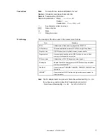
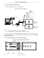
Target cable connector:
Used to connect the connector of the target cable.
USB connector:
Used to connect the USB cable to be connected to the host machine.
Power LED:
Turned on in green when the FPL3 is connected to the host machine.
Status LED:
Blinks in red when the FPL3 is communicating with the target device.
Caution When the Status LED is blinking, communication with the target device is in progress. Do not
disconnect the target cable and USB cable.
MODE switch:
Switches power to be supplied to the target system and sets a clock to be
supplied to the target device.
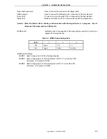
Table 2-1. MODE Switch Setting Table
MODE 1
2
3
VDD
Target
3.3 V
5 V
CLK
Target
8 MHz
16 MHz
[MODE switch setting]
MODE1: Used to supply V
DD
/CLK from the target system.
MODE2: Used to supply power to the target system with 3.3 V V
DD
from the FPL3.
At this time, CLK output is 8 MHz.
MODE3: Used to supply power to the target system with 5 V V
DD
from the FPL3.
At this time, CLK output is 16 MHz.


