background image

English-60

This function can be used to get the monitor status via wireless communication, even when the main power is off. 
Some of the OSD options can also be set using this method.

NOTE:


Sensor position: See 

page 10

.

Please contact your supplier for detailed information. 
Complied with ISO 15693.

Function name

Setting Copy
Setting read and write function
Display information
Security Setting

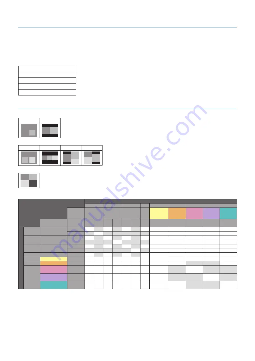
MULTIPICTURE matrix

PICTURE NUMBER: 2 PICTURES

PIP

PBP1

A

B

A

B

PICTURE NUMBER: 3 PICTURES

PIP

PBP1

PBP2

PBP3

A

C

B

C

B

A

C

B

A

B

A

C

PICTURE NUMBER: 4 PICTURES

B

A

C

D

A: PICTURE 1   B: PICTURE 2 

C: PICTURE 3   D: PICTURE 4

PICTURE NUMBER: 2 PICTURES

Picture 2

HDMI1

HDMI2

HDMI3

MP

DisplayPort2 DisplayPort1

OPTION

Connector

HDMI IN1

HDMI IN2

HDMI IN3

DisplayPort 

IN2

DisplayPort 

IN1

Option Board 

slot (SLOT2 

(DP))

Option Board 

slot (SLOT2 

(DP+TMDS))

Option Board 

slot (SLOT2 

(TMDS))

Connector

TERMINAL 

SETTINGS*

1

MODE 

1

MODE 

2

MODE 

1

MODE 

2

MODE 

1

MODE 

2

MODE 

1

2CH

MODE 1

P

icture

 1

HDMI1

HDMI IN1

MODE 1

Yes

No

Yes

No

Yes

No

Yes

Yes

Yes

Yes

[

Yes

MODE 2

No

[

No

No

No

No

No

Yes

Yes

Yes

[

Yes

HDMI2

HDMI IN2

MODE 1

Yes

No

Yes

No

Yes

No

Yes

Yes

Yes

Yes

[

Yes

MODE 2

No

No

No

[

No

No

No

Yes

Yes

Yes

[

Yes

HDMI3

HDMI IN3

MODE 1

Yes

No

Yes

No

Yes

No

Yes

Yes

Yes

Yes

[

Yes

MODE 2

No

No

No

No

No

[

No

Yes

Yes

Yes

[

Yes

MP

MODE 1

Yes

No

Yes

No

Yes

No

Yes

Yes

Yes

Yes

[

Yes

DisplayPort2

DisplayPort IN2

Yes

[

Yes

[

Yes

[

Yes

Yes

Yes

Yes

[

Yes

DisplayPort1

DisplayPort IN1

Yes

[

Yes

[

Yes

[

Yes

Yes

Yes

No

No

Yes

OPTION

Option Board slot 

(SLOT2 (DP))

Yes

[

Yes

[

Yes

[

Yes

Yes

No

Yes

No

No

Option Board slot 

(SLOT2 (DP+TMDS))

2CH

Yes

[

Yes

[

Yes

[

Yes

Yes

No

No

[

No

Option Board slot 

(SLOT2 (TMDS))

MODE 1

Yes

[

Yes

[

Yes

[

Yes

Yes

Yes

No

No

Yes

*: PBP1: Yes, PIP: No
*1: SLOT2 CH SETTING for SLOT2 (DP+TMDS)

INTELLIGENT WIRELESS DATA

Summary of Contents for MultiSync V554Q-AVT2

Page 1: ...MODEL V554Q Please find your model name in the label on the rear side of monitor User s Manual Large Format Display MultiSync V554Q ...

Page 2: ...1 File display screen English 23 Slideshow display English 24 Media Player settings English 24 NETWORK OTHER SETTINGS English 25 Using SHARED SD card SETTINGS English 26 Using CONTENTS COPY English 27 Using Emergency contents English 27 Information OSD English 27 Picture Mode English 28 OSD On Screen Display Controls English 31 INPUT English 32 PICTURE English 32 AUDIO English 34 SCHEDULE English ...

Page 3: ...n helpful How to Identify and Resolve Radio TV Interference Problems This booklet is available from the U S Government Printing Office Washington D C 20402 Stock No 004 000 00345 4 SUPPLIER S DECLARATION OF CONFORMITY This device complies with Part 15 of FCC Rules Operation is subject to the following two conditions 1 This device may not cause harmful interference and 2 this device must accept any...

Page 4: ...nce with the table below If a power cord is not supplied with this equipment please contact NEC For all other cases please use the power cord with the plug style that matches the power socket where the monitor is located The compatible power cord corresponds to the AC voltage of the power outlet and has been approved by and complies with the safety standards in the country of purchase This equipme...

Page 5: ...wiping clean the ventilation holes a minimum of once a month To ensure the monitor s reliability please clean the ventilation holes at the rear side of the cabinet at least once a year to remove dirt and dust When using a LAN cable do not connect to a peripheral device with wiring that might have excessive voltage Do not use the monitor in high temperature humid dusty or oily areas Do not use the ...

Page 6: ... deterioration or discoloration on the LCD panel surface Cleaning the Cabinet Unplug the power supply Gently wipe the cabinet with a soft cloth To clean the cabinet dampen the cloth with a neutral detergent and water wipe the cabinet and follow with a dry cloth NOTE DO NOT clean with benzene thinner alkaline detergent alcoholic system detergent glass cleaner wax polish cleaner soap powder or insec...

Page 7: ...ty To ensure safe installation use two or more brackets to mount the unit Mount the unit to at least two points on the installation location Please note the following when mounting on wall or ceiling CAUTION When using mounting accessories other than those that are NEC approved they must comply with the VESA compatible FDMlv1 mounting method NEC recommends mounting interfaces that comply with UL16...

Page 8: ...tioning around the monitor so that heat can properly dissipate away from the monitor and from the mounting equipment Mounting on ceilings Ensure that the ceiling is strong enough to support the weight of the unit and the mounting equipment over time against earthquakes unexpected vibrations and other external forces Be sure the unit is mounted to a solid structure within the ceiling such as a supp...

Page 9: ...t is larger than the monitor s screen area on the table before laying the monitor face down Make sure there is nothing on the table that can damage the monitor When using mounting accessories other than NEC compliant and approved they must comply with the VESA Flat Display Mounting Interface Standard FDMI NOTE Prior to installation place the monitor face down on a flat even surface that is larger ...

Page 10: ... on the stand pole are indicators of the height adjustment Figure 3 Please adjust the pipe to the lines Figure 3 V554Q High Low Pipe Adjust the pipe to a line 2 Please install the stand pole and the pipe with included screws Please screw the two screw holes at the pipe Figure 4 Pipe Figure 4 Stand pole CAUTION Installing the monitor at the wrong height can cause tipping Please install your monitor...

Page 11: ...n selected with the SET button F p Button up button Activates the OSD menu when the OSD menu is turned off Acts as p button to move the highlighted area up to select adjustment items within the OSD menu G q Button down button Activates the OSD menu when the OSD menu is turned off Acts as q button to move the highlighted area down to select adjustment items within the OSD menu H MENU EXIT Button Ac...

Page 12: ... port USB Type B Connect external equipment such as a computer To control the monitor from connected external equipment please use this port USB CM1 2A Power supply port USB CM2 Service port Please do not connect devices USB functionality is available when the optional Raspberry Pi Compute Module Interface Board and Raspberry Pi Compute Module are installed USB MP USB storage device reader for use...

Page 13: ...ta Sensor Sensor for wireless communication to the monitor for information and settings See page 60 T Option Speaker Mounting Hole NOTE Please contact your supplier for a list of compatible speakers Raspberry Pi Compute Module Slot Slot for installing a Raspberry Pi Compute Module Interface Board and Raspberry Pi Compute Module Please refer to https www nec display com dl en manual raspberrypi for...

Page 14: ...button when you make a selection POINT ZOOM When OSD is not shown this button acts as point zoom button LVOLUME Button Increases or decreases the audio output level M CH ZOOM Button 1 Increases or decreases the POINT ZOOM level Please refer to POINT ZOOM See page 58 N GUIDE Button 1 O MUTE Button Turns on off the mute function P PICTURE MODE Button Selects the picture mode HIGHBRIGHT STANDARD sRGB...

Page 15: ...ictures PICTURE ASPECT Button Selects active picture frame aspect NOTE Enable to change each multi picture size by pressing SET POINT ZOOM button during multi picture mode REMOTE ID Button Activates the REMOTE ID function See page 46 MTS Button 1 1 This button s action depends on which Option Board you are using Refer to the Option Board s user s manual for further information NOTE The buttons wit...

Page 16: ... monitor face down 2 Install the remote control batteries The remote control is powered by two 1 5V AAA batteries To install or replace batteries 1 Press and slide to open the cover 2 Align the batteries according to the and indications inside the case 3 Replace the cover CAUTION Incorrect usage of batteries can result in leaks or bursting NEC recommends the following battery use Place AAA size ba...

Page 17: ...puter switch on the monitor power first 7 Operate the attached external equipment Select the input source for the attached equipment to show the image signal on screen 8 Adjust the sound Make volume adjustments when required 9 Adjust the picture settings See page 32 If necessary make adjustments to such as the backlight or contrast in the OSD PICTURE menu 10 Recommended Adjustments To reduce the r...

Page 18: ...nnecting or disconnecting a USB storage device or a microSD memory card to avoid data corruption Wiring Diagram USB1 USB2 USB CM1 2A USB CM2 USB MP Dotted lines other signal Solid lines video signal Dashed lines audio signal USB storage device Stereo Amplifier USB port Type A USB devices such as USB camera or USB memory Devices that require power supply Ex MultiPresenter Stick USB port Type B USB ...

Page 19: ...ter with HDMI Please use an HDMI cable with the HDMI logo It may take a moment for the signal to appear after turning on the computer Some display cards or drivers may not display an image correctly When you use a computer with HDMI please set OVER SCAN to AUTO or OFF as display drivers may not be fully compatible and may not display an image correctly see page 33 To output HDMI audio set HDMI1 HD...

Page 20: ...rking In this case please check user s manual of your computer or device or contact your supplier for detailed information Before turning off the main power switch of the monitor or shutting down Windows please turn off the USB function and remove the USB cable from the monitor You may lose data when the computer crashes It may take a few seconds until the monitor recognizes the USB input Do not d...

Page 21: ... on the Control Panel or Remote Control to turn on the monitor NOTE The Main Power switch must be in the ON position in order to power up the monitor using the remote control or the button on the Control Panel Main Power Switch OFF ON Button Using the remote control POWER ON button ...

Page 22: ...NPUT DETECT is set to a setting except for NONE USB POWER is set to ON DisplayPort in the TERMINAL SETTINGS is set to MST Glowing amber No AV signal input has been detected by the monitor during the period of time you set with network signal input Blinking amber No AV signal input has been detected by the monitor during the period of time you set no network signal input Glowing red Turn off the mo...

Page 23: ...e displayed in the Sorted order NOTE Only 1 USB storage device can be recognized by the viewer A window will appear when you press the control panel buttons while the Media Player is active You can select to control either the OSD menu or the Media Player from the window that opens If Media Player contents are played while TILE MATRIX is active the image play timing might have a gap within monitor...

Page 24: ...card in the FAT32 format or FAT16 format Refer to the computer s instruction user s manual or Help file on how to format a microSD memory card Information Up to 32GB microSDHC is supported NOTE The monitor is not guaranteed to work with all microSD memory card sold commercially microSD with CPRM is not supported microSD UHS 1 or UHS 2 are not supported When inserting a microSD memory card please m...

Page 25: ...SB MP See page 18 File display screen The files can be displayed using either icons or thumbnails in the Media Player Icon display RETURN Goes back one level higher PAGE UP Displays a list of the previous files PAGE DOWN Displays a list of the next files SETTINGS Displays the setting screen THUMBNAILS ICON Switches between thumbnail display and icon display SORT Changes the order to display files ...

Page 26: ...TO or MANUAL INTERVAL Sets interval time REPEAT Check the check box to repeat slideshow AUDIO FILE Selects an audio file BGM Check the check box to enable BGM PLAY END SCREEN Selects a setting for when the slideshow finishes BLACK SCREEN When the slideshow finishes a black screen is displayed FILE LIST When the slideshow finishes it goes back to the file list screen SAVE LAST SCREEN When the slideshow...

Page 27: ...by controlling the monitor Menu Function ENABLE Check the checkbox to enable SHARED FOLDER SETTINGS SHARED FOLDER Set the IP address of the network shared folder location that contains the files for copying to the microSD card USER NAME Set USER NAME which is used when connecting the monitor to the shared folder PASSWORD Set password Please press OK to activate settings in the SHARED FOLDER SETTING...

Page 28: ...dure 1 Open the Monitor LAN control of the network connected monitor then select SD CARD VIEWER 2 Select SEARCH to display the IP ADDRESS of the currently connected monitor and all compatible monitors on the same network 3 Select the IP ADDRESS of the currently connected monitor 4 Enable upload delete and sort files that are saved in the microSD memory card connected to the monitor Function 1 SELE...

Page 29: ...ge capacity is not enough to copy selected folders When contents copy has occurred previous data that was saved in the microSD memory card is deleted Only devices connected to the monitor are shown When the monitor is copying a folder the LED indicator blinks in red When the monitor is in this condition do not eject the microSD memory card from the monitor and do not turn off the monitor s main po...

Page 30: ...ting systems many smart phones and other digital cameras Recommended setting for general color management Adobe RGB SIM Provides a standard color space used in high end graphics applications such as professional digital still cameras and imaging eciRGB_v2 SIM Color setting recommended by ECI The European Color Initiative DCI SIM Color setting for digital cinema REC Bt709 Color setting for High def...

Page 31: ...n of the user including those with color vision deficiency there will be a variation in how the screen s color is seen and experienced A simulation is used to illustrate the view of those with a color vision deficiency It is not their actual view The simulation is a reproduction of those with a strong color vision mode of type P type D or type T People with a slight color vision deficiency will ex...

Page 32: ...tion Board you are using 2 This input is available when the optional Raspberry Pi Compute Module Interface Board and Raspberry Pi Compute Module are installed For MP STANDARD CINEMA CUSTOM1 CUSTOM2 HIGHBRIGHT PRESET types PRESET PURPOSE HIGH BRIGHT Highest brightness setting STANDARD Standard setting sRGB The standard color space used for the Internet Windows operating systems and digital cameras ...

Page 33: ...A sRGB CUSTOMVALUE WHITE 6500K WHITE x y x 0 279 y 0 292 RED x y x 0 683 y 0 306 GREEN x y x 0 191 y 0 709 BLUE x y x 0 153 y 0 044 COLORVISIONEMU OFF UNIFORMITY OFF METAMERISM ON OFF COLORCONTROL R 0 Y 0 G 0 C 0 B 0 M 0 Goto Adjustment Select Return Close MULTI INPUT OPTION C MODULE Input source Main Menu Icons Main Menu Item Sub Menu Key Guide Adjustment Settings Remote Control Press or to navig...

Page 34: ... gamma can be adjusted PROGRAMMABLE1 2 3 A programmable gamma curve can be loaded using optional NEC software AUTO HDR SELECT HDMI input only GAMMA correction of HDR signal automatically changes to HDR ST2084 PQ or HDR HYBRID LOG COLOR 2 COLOR Adjusts the color depth of the screen Press or to adjust COLOR TEMPERATURE 1 Adjusts the color temperature of the entire screen A low color temperature will...

Page 35: ...tside of the active screen area are not shown The reduced image may have some image degradation ZOOM Maintains the aspect ratio while zooming HZOOM Horizontal zoom value VZOOM Vertical zoom value H POS Horizontal position V POS Vertical position ADVANCED OVER SCAN HDMI1 HDMI2 HDMI3 MP OPTION 1 inputs only Some video formats may require different scanning modes in order to best display the image ON...

Page 36: ...STEREO adjust the L R volume balance Press the button to move the stereo sound image to right Press the button to move the stereo sound image to left NOTE BALANCE is not available if MONO is set at STEREO MONO SURROUND Artificial surround sound NOTE LINE OUT is disabled when this function is set to ON EQUALIZER TREBLE Accentuate or reduce the high frequency range of audio signals Press the button ...

Page 37: ...le is repeating every day EVERY WEEK Select this setting if the schedule is repeating every week WEEKDAY Select this setting if the schedule is on a weekday This item is set by the WEEKEND and the HOLIDAY settings A day which is not selected at WEEKEND and HOLIDAY settings is set as a weekday WEEKEND Select this setting if the schedule is on a weekend Schedule operates on the date that is set at W...

Page 38: ...lable when MULTI PICTURE is OFF When changing input signal for the active picture after selecting an input press the SET button PICTURE SIZE 1 2 4 Sets the Active Picture size Press the SET POINT ZOOM button to adjust the picture size Press or CH to expand Press or CH to reduce NOTE This function is not available when MULTI PICTURE is set to 4 PICTURES Depends on the setting at MULTI PICTURE MODE ...

Page 39: ...3 you cannot set OPTION slot 2 type PC option DP to any priority settings If you set OPTION slot 2 type PC option DP to Priority 1 or 2 or 3 you cannot set DisplayPort1 to any priority settings INPUT CHANGE Sets input change speed If QUICK is set speed of changing input is faster but this setting may cause image distorted while switching signals Selecting SUPER enables high speed switching between...

Page 40: ... 14 characters including Space A Z 0 9 and some symbols RESET Resets the following settings within the OSD menu back to factory setting OSD TIME OSD POSITION INFORMATION OSD OSD TRANSPARENCY MULTI DISPLAY AUTO TILE MATRIX SETUP TILE MATRIX allows one image to be displayed over multiple screens up to 100 through a distribution amplifier Allows auto setting of TILE MATRIX by inputting the number of ...

Page 41: ...D IP SETTING window is shown Do not connect network devices between the monitors connected with LAN SETTING ITEM Select an item from MONITOR ID IP ADDRESS and ID and IP MONITOR ID When YES is selected the monitor ID numbers are set automatically for all monitors IP ADDRESS Set the first octet to the third octet at BASE ADDRESS The fourth octet is automatically set from 1 and counting up to the num...

Page 42: ...r Background color of the Media Player window is also changed POWER ON DELAY Adjusts the delay time between being in standby mode and entering power on mode DELAY TIME POWER ON DELAY can be set between 0 and 50 seconds LINK TO ID When ON is selected the delay time is linked with the Monitor ID It takes more time when there are a large number of IDs ALERT MAIL Set ON to activate alert mail See page...

Page 43: ...r to be unlocked The unselected buttons are locked When LOCK is selected all INPUT buttons are locked CHANNEL To lock channel buttons on the remote control select it to LOCK then press ACTIVE channel CH ZOOM button and button are locked KEY LOCK SETTINGS Prevents the monitor from being controlled by the buttons on the monitor When ACTIVATE is selected all of the settings are activated NOTE KEY LOC...

Page 44: ...ighting level is high HUMAN SENSING 2 HUMAN SENSING has three settings NOTE POWER SAVE is disabled when AUTO OFF or CUSTOM is selected in HUMAN SENSING HUMAN SENSING is released if INPUT DETECT is set while HUMAN SENSING is active DISABLE No human sensing AUTO OFF At the preset time when no person is detected BACKLIGHT and VOLUME automatically go into OFF When a person comes near the monitor again...

Page 45: ...s no connected HDMI CEC audio device to the monitor SEARCH DEVICE Searches the HDMI CEC device connected to the monitor When search is successful the connected HDMI CEC device s type and registered device name are shown When search has been completed or failed the SEARCH DEVICE is set to NO automatically To retry the SEARCH DEVICE set it to YES again After detecting HDMI CEC devices you can switch...

Page 46: ...ful to avoid resetting all items inadvertently COMPUTE MODULE COMPUTE MODULE When a Raspberry Pi Compute Module Interface Board and Raspberry Pi Compute Module are installed additional OSD menu items will be available for configuring the related settings Please do not change settings in COMPUTE MODULE yourself POWER POWER SUPPLY Controls power to the Compute Module AUTO POWER ON When set to ENABLE...

Page 47: ...nitors LCD monitors image persistence is not permanent but constant images being displayed for a long period of time should be avoided To alleviate image persistence turn off the monitor s main power or set it to standby for as long as the previous image was displayed For example if an image was on the monitor for one hour and a residual image remains the monitor s main power should be turned off ...

Page 48: ...onitors in range 1 On the remote control press and hold down the REMOTE ID SET button while using the keypad to input the REMOTE CONTROL ID number 0 2 All monitors within range of the remote control will now respond to keypad press NOTE When the REMOTE ID is set to 0 pressing REMOTE ID SET will make all monitors within range of the remote signal display their Monitor ID on screen This way you can ...

Page 49: ...ained have a limit to the connectable monitors Please execute AUTO ID see page 39 before manually specifying the ID number or control by the specified ID number Main Monitor Sub Monitors Connector Connector IN OUT IN OUT RS 232C LAN2 LAN1 LAN2 REMOTE IN LAN1 Connection LAN Cable Next monitor LAN Cable LAN1 LAN2 LAN1 LAN2 Multiple Monitors Connection ...

Page 50: ... reverse order the com port may not work When controlling the monitor connected with an RS 232C cable please refer to the Control command See page 56 or see the External_Control pdf file on the CD ROM supplied with the monitor RS 232C Cable Computer RS 232C NOTE If your computer is equipped only with a 25 pin serial port connector a 25 pin serial port adapter is required Contact your supplier for ...

Page 51: ...his monitor uses RXD TXD and GND lines for RS 232C control The reverse type cable null modem cable not included should be used for RS 232C control 2 PIN ASSIGNMENT RS 232C input output 1 6 5 9 D SUB 9P Monitor side Pin No Name 1 NC 2 RXD 3 TXD 4 NC 5 GND 6 NC 7 NC 8 NC 9 NC This monitor uses RXD TXD and GND lines for RS 232C control ...

Page 52: ...se refer to the help files and the other information provided in your software To access the HTTP server launch a web browser on a computer connected to the same network as the monitor and enter the following URL in the web address field Network Setting http the Monitor s IP address index html HINT The default IP address is assigned automatically to the monitor The exclusive application can be dow...

Page 53: ...een configured in the HOSTS file of the computer being used you can then access the network settings of the monitor via this host name by using a compatible browser Example 1 When the host name of the monitor has been set to pd nec co jp access is gained to the network setting by specifying http pd nec co jp index html for the address or the entry column of the URL Example 2 When the IP address of...

Page 54: ...n MANUAL is selected for IP SETTING NOTE Set as 0 0 0 0 to delete the setting DNS Set for IP ADDRESS setting of DNS server AUTO The DNS server connected to the monitor will automatically assign its IP address MANUAL Manually enter the IP address of the DNS server that is connected with the monitor PRIMARY DNS Enter the primary DNS server settings of the network connected with the monitor NOTE Ente...

Page 55: ...ging into the authentication server when authentication is required for the email transmission Up to 60 alphanumeric characters can be used PASSWORD This sets the password for logging into the authentication server when authentication is required for the email transmission Up to 60 alphanumeric characters can be used TEST MAIL Click on this button to send a test email to check if your settings are...

Page 56: ...ff for the detection from AMX Device Discovery when connecting to a network supported by an AMX s NetLinx control system HINT When using a device that supports AMX Device Discovery all AMX NetLinx control systems will recognize the device and download the appropriate Device Discovery Module from an AMX server Selecting ENABLE AMX Device Discovery will detect the device Selecting DISABLE AMX Device...

Page 57: ... is PJLink PJLink is a standardization of protocol used for controlling devices of different manufacturers This standard protocol was established by Japan Business Machine and Information System Industries Association JBMIA in 2005 The device supports all commands of PJLink PD LIST Information Click on PD LIST on the left column below HOME Shows a list of monitor IDs and IP addresses of multiple m...

Page 58: ...0d Input Source Select HDMI3 01 30 41 30 45 30 41 02 30 30 36 30 30 30 38 32 03 78 0d or 01 30 41 30 45 30 41 02 31 31 30 36 30 30 38 32 03 78 0d Input Source Select MP 01 30 41 30 45 30 41 02 30 30 36 30 30 30 38 37 03 7D 0d or 01 30 41 30 45 30 41 02 31 31 30 36 30 30 38 37 03 7D 0d Input Source Select OPTION 01 30 41 30 45 30 41 02 30 30 36 30 30 30 30 44 03 06 0d or 01 30 41 30 45 30 41 02 31 ...

Page 59: ...tem Standby If the monitor is set to standby using the wireless remote control supplied with the monitor HDMI CEC supported devices also go into standby at the same time If the monitor goes into standby while an HDMI CEC supported device is recording the device is kept on Please refer to the user s manual supplied with the HDMI CEC supported device for further information By using buttons select A...

Page 60: ...ept for NONE MULTI PICTURE MODE SCREEN SAVER SUPER in INPUT CHANGE TILE MATRIX and TEXT TICKER When DYNAMIC or ZOOM is selected in ASPECT the image will change to FULL Then start with POINT ZOOM After exiting POINT ZOOM ASPECT will return to the previous ASPECT settings When ASPECT is changed during the POINT ZOOM operation DYNAMIC and ZOOM will be set to FULL image The magnifier icon does not mov...

Page 61: ...ent 01h Proof of Play event is last power on time 10h MEDIA PLAYER is stop 11h MEDIA PLAYER is start 12h MEDIA PLAYER is pause 13h MEDIA PLAYER error occur 20h Contents Copy from USB 21h Contents Copy form network folder 30h Contents Copy Success 31h Contents Copy Error No media 32h Contents Copy Error Connect error 33h Contents Copy Error Out of disk space 34h Contents Copy Error Read Write error...

Page 62: ...N1 Option Board slot SLOT2 DP Option Board slot SLOT2 DP TMDS Option Board slot SLOT2 TMDS Connector TERMINAL SETTINGS 1 MODE 1 MODE 2 MODE 1 MODE 2 MODE 1 MODE 2 MODE 1 2CH MODE 1 Picture 1 HDMI1 HDMI IN1 MODE 1 Yes No Yes No Yes No Yes Yes Yes Yes Yes MODE 2 No No No No No No Yes Yes Yes Yes HDMI2 HDMI IN2 MODE 1 Yes No Yes No Yes No Yes Yes Yes Yes Yes MODE 2 No No No No No No Yes Yes Yes Yes H...

Page 63: ...No No No MODE 2 No No No No No No No No No No No No HDMI2 HDMI IN2 MODE 1 No No No No No No No No No No No No MODE 2 No No No No No No No No No No No No HDMI3 HDMI IN3 MODE 1 No No No No No No No No No No No No MODE 2 No No No No No No No No No No No No MP MODE 1 No No No No No No No No No No No No DisplayPort2 DisplayPort IN2 No No No No No No No Yes Yes Yes No Yes DisplayPort1 DisplayPort IN1 No...

Page 64: ...MI2 HDMI IN2 MODE 1 No No Yes No No No Yes Yes Yes Yes No Yes MODE 2 No No No No No No No No No No No No HDMI3 HDMI IN3 MODE 1 No No No No Yes No Yes Yes Yes Yes No Yes MODE 2 No No No No No No No No No No No No MP MODE 1 Yes No Yes No Yes No Yes Yes Yes Yes No Yes DisplayPort2 DisplayPort IN2 Yes No Yes No Yes No Yes Yes Yes Yes No Yes DisplayPort1 DisplayPort IN1 Yes No Yes No Yes No Yes Yes Yes...

Page 65: ...o No No No No No No No No No No No HDMI2 HDMI IN2 MODE 1 Yes No Yes No Yes No Yes Yes No Yes No No MODE 2 No No No No No No No No No No No No HDMI3 HDMI IN3 MODE 1 Yes No Yes No Yes No Yes Yes No Yes No No MODE 2 No No No No No No No No No No No No MP MODE 1 Yes No Yes No Yes No Yes Yes No Yes No No DisplayPort2 DisplayPort IN2 Yes No Yes No Yes No Yes Yes No Yes No No DisplayPort1 DisplayPort IN1...

Page 66: ...o No No HDMI2 HDMI IN2 MODE 1 Yes No Yes No Yes No Yes Yes Yes No No Yes MODE 2 No No No No No No No No No No No No HDMI3 HDMI IN3 MODE 1 Yes No Yes No Yes No Yes Yes Yes No No Yes MODE 2 No No No No No No No No No No No No MP MODE 1 Yes No Yes No Yes No Yes Yes Yes No No Yes DisplayPort2 DisplayPort IN2 Yes No Yes No Yes No Yes Yes Yes No No Yes DisplayPort1 DisplayPort IN1 Yes No Yes No Yes No Y...

Page 67: ...o No No No No No HDMI2 HDMI IN2 MODE 1 No No Yes No Yes No No Yes Yes Yes No Yes MODE 2 No No No No No No No No No No No No HDMI3 HDMI IN3 MODE 1 Yes No Yes No Yes No Yes Yes Yes Yes No Yes MODE 2 No No No No No No No No No No No No MP MODE 1 No No No No Yes No Yes Yes Yes Yes No Yes DisplayPort2 DisplayPort IN2 Yes No Yes No Yes No Yes Yes Yes Yes No Yes DisplayPort1 DisplayPort IN1 Yes No Yes No...

Page 68: ...No No No No Yes Yes No No Yes HDMI2 HDMI IN2 MODE 1 Yes No Yes No Yes No Yes Yes Yes No No Yes MODE 2 No No No No No No No Yes Yes No No Yes HDMI3 HDMI IN3 MODE 1 Yes No Yes No Yes No Yes Yes Yes No No Yes MODE 2 No No No No No No No Yes Yes No No Yes MP MODE 1 Yes No Yes No Yes No Yes Yes Yes No No Yes DisplayPort2 DisplayPort IN2 Yes No Yes No Yes No Yes Yes Yes No No Yes DisplayPort1 DisplayPor...

Page 69: ...Board slot SLOT2 TMDS MODE 1 Yes No Yes No Yes No Yes Yes Yes No No Yes 1 SLOT2 CH SETTING for SLOT2 DP TMDS PICTURE NUMBER 4 PICTURES Only one input signal can be selected from within a group One of five groups is displayed on each screen The same group can be selected more than once Group A Group B Group C Group D Group E DisplayPort1 OPTION DP DisplayPort2 HDMI1 HDMI2 HDMI3 MP HDMI1 HDMI2 HDMI3...

Page 70: ...es innovative power saving methods that allow the monitor to shift to a lower power consumption level when on but not in use saving two thirds of your monitor energy costs reducing emissions and lowering the air conditioning costs of the workplace FullScan Capability Allows you to use the entire screen area in most resolutions significantly expanding image size VESA Standard FDMIv1 Mounting Interf...

Page 71: ...l repeater or distributor or a long cable this may cause image roughness or blink for a moment In this case please connect the cable to the monitor directly without using a repeater or a distributor or replace the cable with a higher quality cable Using a twisted pair extender may cause image roughness depending on the environment where the monitor is in or the cable you are using For further info...

Page 72: ...function is not working properly The SCHEDULE function will be disabled when the OFF TIMER is set If the OFF TIMER function is enabled and the power to the monitor is turned off when the power supply is interrupted unexpectedly then the OFF TIMER will be reset Snowy Picture Poor Sound in TV Check antenna cable connection Use new cable if necessary The USB Hub does not operate Check to make sure th...

Page 73: ... PCM 32 44 1 48 KHz 16 20 24bit AUDIO Output Stereo Mini Jack Analog Audio Stereo L R 0 5 Vrms Speaker Output External Speaker Jack 15 W 15 W 8 ohm Internal Speaker 10 W 10 W Stereo Control RS 232C In LAN Remote IN 9 Pin D sub RJ 45 10 BASE T 100 BASE TX x 2 Stereo Mini Jack 3 5 mm Ø SD card Hub Port microSD card Up to 32GB microSDHC is supported USB Hub USB1 USB2 USB CM1 2A USB CM2 USB MP USB 2 0...

Page 74: ...c information on recycling facilities can be found on our following websites https www nec display solutions com p greenvision en greenvision xhtml in Europe https www nec display com in Japan or https www necdisplay com in USA Energy Saving This monitor features an advanced energy saving capability When a Display Power Management signal is sent to the monitor the Energy Saving mode is activated T...

Page 75: ...le follow applicable legislation or agreement you may have The mark on electrical and electronic products may only apply to the current European Union Member States Outside the European Union If you wish to dispose of used electrical and electronic products outside the European Union please contact your local authority and ask for the correct method of disposal For EU The crossed out wheeled bin i...

Page 76: ...WWW MPEGLA COM 2 MPEG 4 Visual THIS PRODUCT IS LICENSED UNDER THE MPEG 4 VISUAL PATENT PORTFOLIO LICENSE FOR THE PERSONAL AND NON COMMERCIAL USE OF A CONSUMER FOR i ENCODING VIDEO IN COMPLIANCE WITH THE MPEG 4 VISUAL STANDARD MPEG 4 VIDEO AND OR ii DECODING MPEG 4 VIDEO THAT WAS ENCODED BY A CONSUMER ENGAGED IN A PERSONAL AND NONCOMMERCIAL ACTIVITY AND OR WAS OBTAINED FROM A VIDEO PROVIDER LICENSE...

Reviews: