English-5
English
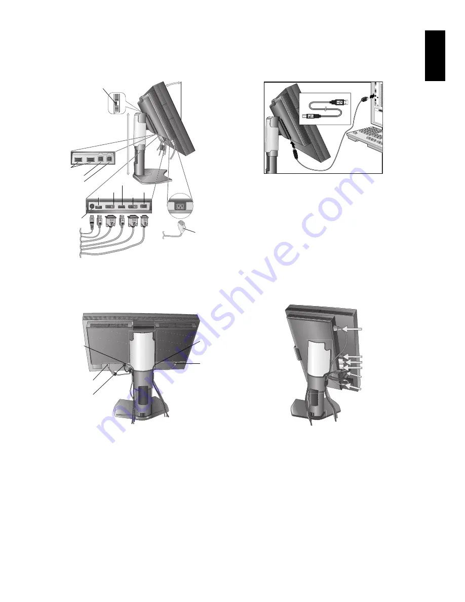
4. Connect all cables to the appropriate connectors (
Figure C.1
). When using the USB cable, connect the B type connector
to the USB upstream port on the right back side of the monitor and the A type connector to the downstream port on the
computer (
Figure C.1a
). If using the cord from a USB device, plug into one of the downstream ports of the monitor.
NOTE:
Incorrect cable connections may result in irregular operation, damage display quality/components of LCD module
and/or shorten the module’s life.
Figure C.1
Highest
Stand
Position
Power cord
30° Tilt
DC-OUT*
* NEC optional product attachment (except PA301W).
Do not use this connector unless specifi ed.
DVI-1
DisplayPort*
3
USB downstream
USB upstream1
USB upstream2
DVI-2
D-SUB*
1
Figure C.1a
A Type
B Type
A Type
B Type
USB downstream*
2
DisplayPort-2*
4
5. To keep the cables neatly organized, place them into the cable management system that is built into the stand.
Place the cables in the hooks fi rmly and evenly (
Figure C.2
and
Figure C.3
).
6. Please check that you can still rotate, raise and lower the monitor screen when you have installed the cables.
Figure C.2
Figure C.3
USB Cable
Power Cord
DVI-1 Cable
D-SUB Cable*
1
Power Cord
DVI-1/DVI-2 Cables
D-SUB Cable*
1
USB Cable
DisplayPort
Cable
DisplayPort Cable
*1 Only for PA231W/PA241W.
*2 Connect sensor to this port for self calibration (PA301W). (See page 34)
*3 DisplayPort-1 for PA301W.
*4 Only for PA301W.


