background image

English-8

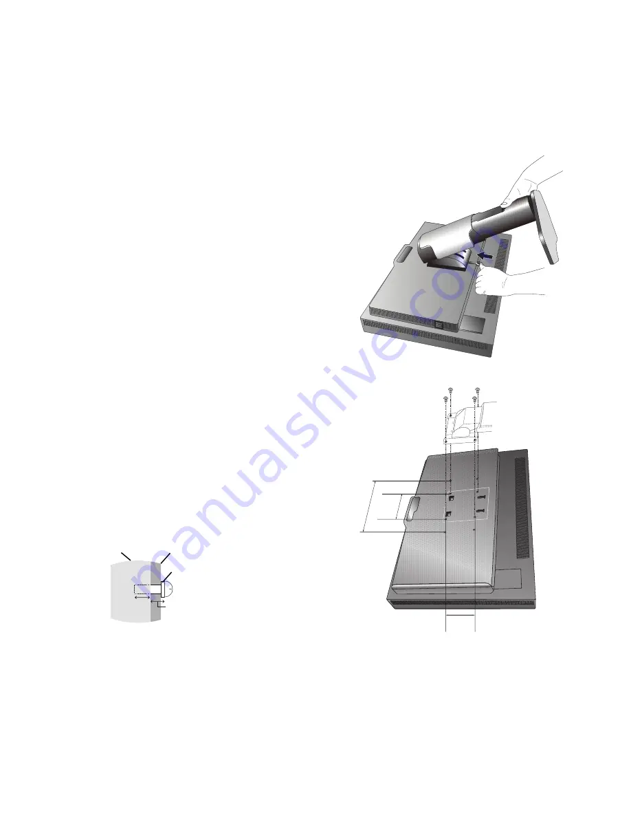
Figure S.1

100 mm

100 mm

Figure F.1

Weight of LCD assembly:  7.0 kg (PA231W)
 

7.4 kg (PA241W)


9.6 kg (PA271W)


12.5 kg (PA301W)

Mount Flexible arm

This LCD monitor is designed for use with a fl exible arm.

1.  Follow the instructions on how Remove Monitor Stand for 

Mounting to remove the stand.

2.  Using the 4 screws from the stand removal and attach the arm to 

the monitor (

Figure F.1

).

Caution: 

Use ONLY the screws (4 pcs) that are included or the 
screws M4 size (Length: thickness of bracket and  
10-12 mm) when mounting to avoid damage to the monitor 
and stand. To fulfi l the safety requirements the monitor 
must be mounted to an arm which guaranties the 
necessary stability under consideration of the weight of 
the monitor. The LCD monitor should only be used with 
an approved arm (e.g. GS mark).

Mounting
Bracket

Screw

Washer

Unit

10-12 mm

Thickness 
of bracket 
and washer

NOTE: 

Tighten all screws. 
(recommended Fasten Force: 98 - 137N•cm)

*2  Only for PA271W/PA301W.

200 mm*

2

Flexible Arm Installation

This LCD monitor is designed for use with a fl exible arm.

To prepare the monitor for alternate mounting purposes:

NOTE: 

For PA301W, the monitor must be installed or moved by two or more people.

• 

Follow the instructions provided by the manufacturer of the display mount.

• 

To meet the safety requirements, the monitor must be mounted to an arm that supports the weight of the monitor. 
See pages 26-29 for details on each model. Remove the monitor stand before mounting.

Remove Monitor Stand for Mounting

To prepare the monitor for alternate mounting purposes:

1.  Disconnect all cables.

2.  Place hands on each side of the monitor and lift up to the highest position.

3.  Place monitor face down on a non-abrasive surface (

Figure S.1

).

4.  Place one hand around the base and one hand on the Quick Release Lever. 

Push and hold the Quick Release Lever in the direction indicated by the arrows 
(

Figure S.1

).

5.  Lift up the stand to unhook it from the monitor (

Figure S.1

). 

The monitor can now be mounted using an alternate method. 
Reverse process to reattach stand.

NOTE: 

Handle with care when removing monitor stand.

Summary of Contents for MultiSync PA231W

Page 1: ...MultiSync PA231W MultiSync PA241W MultiSync PA271W MultiSync PA301W User s Manual ...

Page 2: ...nction English 15 Advanced OSD English 16 Recommended use English 24 Specifications PA231W English 26 Specifications PA241W English 27 Specifications PA271W English 28 Specifications PA301W English 29 Features English 30 Troubleshooting English 31 Using the Auto Brightness function English 33 Self Calibration English 34 White Point Matching Copy English 36 TCO 03 English 38 TCO Displays 5 English ...

Page 3: ...l Directive 2004 108 EC EN 55022 EN 61000 3 2 EN 61000 3 3 EN 55024 Council Directive 2009 125 EC EC No 1275 2008 EN 62301 2005 and marked with NEC Display Solutions Ltd 4 13 23 Shibaura Minato Ku Tokyo 108 0023 Japan Windows is a registered trademark of Microsoft Corporation NEC is a registered trademark of NEC Corporation ErgoDesign is a registered trademark of NEC Display Solutions Ltd in Austr...

Page 4: ...lar installation If this equipment does cause harmful interference to radio or television reception which can be determined by turning the equipment off and on the user is encouraged to try to correct the interference by one or more of the following measures Reorient or relocate the receiving antenna Increase the separation between the equipment and receiver Connect the equipment into an outlet on...

Page 5: ...o Signal Cable DVI D to DVI D cable 1 Video Signal Cable Mini D SUB 15 pin to Mini D SUB 15 pin only for PA231W PA241W DisplayPort cable USB Cable Setup Manual CD ROM Screw x 4 to mount the monitor to a flexible arm page 8 Setup Manual DVI D to DVI D cable 1 DisplayPort cable CD ROM Screws Power Cord 2 Setup Manual Mini D SUB 15 pin to Mini D SUB 15 pin only for PA231W PA241W USB Cable NOTE This m...

Page 6: ...dapter not included to the computer then attach the 15 pin mini D SUB signal cable to the Macintosh cable adapter Figure A 3 NOTE Some Macintosh systems do not require a Macintosh cable adapter For a PC with DisplayPort output Connect the DisplayPort cable to the connector of the display card in your system Figure A 4 Figure A 1 Figure A 3 Macintosh Cable Adapter not included Figure A 2 Figure A 4...

Page 7: ... except PA301W Do not use this connector unless specified DVI 1 DisplayPort 3 USB downstream USB upstream1 USB upstream2 DVI 2 D SUB 1 Figure C 1a A Type B Type A Type B Type USB downstream 2 DisplayPort 2 4 5 To keep the cables neatly organized place them into the cable management system that is built into the stand Place the cables in the hooks firmly and evenly Figure C 2 and Figure C 3 6 Pleas...

Page 8: ...al setup for most timings For further adjustments use the following OSD controls Auto Contrast Analog input only Auto Adjust Analog input only Refer to the Controls section of this User s Manual for a full description of these OSD controls NOTE If you have any problems please refer to the Troubleshooting section of this User s Manual Figure E 1 Power Button Raise and Lower Monitor Screen The monit...

Page 9: ...nds on each side of the monitor screen and turn clockwise from Landscape to Portrait or counter clockwise from Portrait to Landscape Figure R 1 To rotate OSD menu between landscape and portrait refer to Controls section Figure R 1 Tilt Grasp top and bottom sides of the monitor screen with your hands and adjust the tilt as desired Figure TS 1 Figure TS 1 NOTE Handle with care when tilting the monit...

Page 10: ...y for PA271W PA301W 200 mm 2 Flexible Arm Installation This LCD monitor is designed for use with a flexible arm To prepare the monitor for alternate mounting purposes NOTE For PA301W the monitor must be installed or moved by two or more people Follow the instructions provided by the manufacturer of the display mount To meet the safety requirements the monitor must be mounted to an arm that support...

Page 11: ...nu is off 1 7 UP DOWN Navigates up or down through the OSD Control menu Show Picture Mode menu when not in the OSD Control menu 1 2 8 RESET PIP Resets the OSD back to factory settings in the OSD control menu PIP can be selected when the OSD is not showing 3 Hold the button to show ECO Mode menu while the OSD menu is off 1 9 KEY GUIDE The Key Guide appears on screen when the OSD control menu is acc...

Page 12: ... quality ECO MODE Decreases the amount of power consumed by reducing the brightness level OFF No function MODE1 Decreases the brightness range up to about 160 cd m2 PA231W Decreases the brightness range up to about 200 cd m2 PA241W PA271W PA301W MODE2 Decreases the brightness range up to about 100 cd m2 BLACK Adjusts the black luminance When low settings are selected that cannot be displayed the i...

Page 13: ...e to get as distinct or as soft an image as your prefer and set independently by different timings Color Control Systems PICTURE MODE Change the Picture mode that is most suitable for the type of content that is shown You can change up to 5 types See Advanced menu Tag1 PICTURE MODE page 16 and Using the PICTURE MODE function page 15 for more information WHITE Adjust the white temperature by NATIVE...

Page 14: ...nected equipment has to be restarted VIDEO DETECT Selects the method of video detection when more than one video input is connected FIRST When current video input signal is not present then the monitor searches for a video signal from the other video input port If the video signal is present in the other port then the monitor switches the video source input port to the new found video source autom...

Page 15: ...aits after the last touch of a button to shut off the OSD control menu The preset choices are 10 120 seconds by 5 second increments OSD LOCK OUT This control completely locks out access to all OSD control functions When attempting to activate OSD controls while in the Lock Out mode a screen will appear indicating the OSD controls are locked out There are four types of OSD LOCK OUT OSD LOCK OUT wit...

Page 16: ...GHT key in Current setting item 4 Select Currency Convert Setting item using the UP or DOWN key This initial Euro setting is Germany of OECD 2007 Edition Please check receipt of French s electricity prices or OECD data for French French of OECD 2007 Edition was 0 12 5 Adjust Currency Convert Setting item using the LEFT or RIGHT key Information Provides information about the current resolution disp...

Page 17: ...rightness setting Provides lowest power consumption when kept at factory setting FULL Native display color gamut Suitable for use with color managed applications Use ICC color profile included in the enclosed CD ROM DICOM 3 Medical settings for X ray imaging view Setting that conforms to the DICOM standard for the Grayscale Standard Display Function PROGRAMMABLE For MultiProfiler software or the H...

Page 18: ...r This menu is larger than the normal OSD To exit the advanced menu Turn off and restart the monitor in the normal way To make an adjustment ensure that the tag is highlighted then press SELECT To move to another tag press EXIT then press LEFT or RIGHT to highlight another tag Tag1 PICTURE MODE Selects PICTURE MODE one of 1 to 5 PRESET Sets PICTURE MODE PRESET from the type of PRESET see page 15 B...

Page 19: ...indicator on the OSD will turn magenta RED GREEN BLUE Adjusts color gamut When the selected settings are outside of the LCD gamut the indicator on the OSD will turn magenta COLOR VISION EMU Previews various typical human vision deficiencies and is useful for evaluating how people who have such deficiencies will perceive colors This preview is available in four modes Types P Protanopia D Deutanopia...

Page 20: ...point color matching when the display used side by side with a standard gamut display monitor This feature compensates for the way the human eye perceives colors slightly differently compared to the scientific instrument used to adjust the display during calibration AMBIENT LIGHT COMP Luminance setting depends on ambient light compensation Mostly affects black reproduction NOTE AUTO DIMMING SENSOR...

Page 21: ...he signal is detected then A NTAA does not activate The screen will be blank while the monitor optimizes the signal OPTION Functions the same as ON except that the screen does not go blank when the monitor makes adjustments for changes in signal allowing the monitor to display the new signal faster When using an external switching device to connect 2 or more PCs to the monitor using the ON or OPTI...

Page 22: ...AL Enhanced Alternate setting for non PC devices such as DVD players or game consoles Note Interlaced signals 480i 576i 1080i are not supported If you have any problems please refer to the Troubleshooting section of this User s Manual When EDID EXTENSION has been changed the connected equipment has to be restarted VIDEO DETECT 2 Selects the method of video detection when more than one computer is ...

Page 23: ...in the lock out mode CUSTOM Press RESET and EXIT to enter the CUSTOM Menu Select ENABLE or DISABLE for POWER KEY INPUT SEL HOT KEY BRIGHTNESS PICTURE MODE WARNING RESOLUTION NOTIFIER OSD LOCK OUT To Deactivate the OSD Lock Out function press RESET and EXIT to bring up the LOCK OUT warning Press SELECT SELECT EXIT OSD TRANSPARENCY Adjusts the transparency of the OSD MENU OSD COLOR 2 Tag window fram...

Page 24: ...sk of image persistence MOTION Default OFF Screen image moves periodically in 4 directions in order to reduce the risk of image retention Timing for MOTION can be set so the screen image moves in intervals from every 10 to 900 seconds Timing is set in 10 second increments OPTION Default REDUCED There are two optional selections REDUCED Screen image is reduced to 95 size and is moved periodically i...

Page 25: ...gs in balance CARBON CONVERT SETTING Adjusts the carbon footprint factor in the carbon saving calculation This initial setting is based on the OECD 2008 Edition CURRENCY SETTING 2 Displays electricity pricing available in 6 currency units CURRENCY CONVERT SETTING Adjusts electricity prices electric energy equivalent in the electrical rate saving calculation HOURS RUNNING 2 Show total running time ...

Page 26: ...er servicing to qualified service personnel under the following conditions If the monitor is used in this condition the monitor may cause fall fire and electric shock If the monitor stand has been cracked or peeled If the monitor has been wobbled If the monitor has an unusual odor When the power supply cord or plug is damaged If liquid has been spilled or objects have fallen into the monitor If th...

Page 27: ...atterns on the monitor for long periods of time to avoid image persistence after image effects Get regular eye checkups Ergonomics To realize the maximum ergonomics benefits we recommend the following To avoid eye fatigue adjust the brightness to a moderate setting Place a sheet of white paper next to the LCD screen for luminance reference Do not position the Contrast control to its maximum settin...

Page 28: ...50 1 at 60 Hz 1920 x 1080 at 60 Hz NEC DISPLAY SOLUTIONS cites recommended 1024 x 1280 1 at 60 Hz resolution for optimal display performance 1080 x 1920 1 at 60 Hz 480P 720 x 480 1 at 60 Hz 576P 720 x 576 1 at 50 Hz 720P 1280 x 720 1 at 50 Hz to 60 Hz 1080P 1920 x 1080 1 at 50 Hz to 60 Hz Active Display Area Landscape Horiz Vert Portrait Horiz Vert 509 2 mm 20 0 inches 286 4 mm 11 3 inches 286 4 m...

Page 29: ... 1200 1 at 60 Hz Digital 1680 x 1050 1 at 60 Hz 1920 x 1200 at 60 Hz NEC DISPLAY SOLUTIONS cites recommended 1024 x 1280 1 at 60 Hz resolution for optimal display performance 1200 x 1920 1 at 60 Hz 480P 720 x 480 1 at 60 Hz 576P 720 x 576 1 at 50 Hz 720P 1280 x 720 1 at 50 Hz to 60 Hz 1080P 1920 x 1080 1 at 50 Hz to 60 Hz Active Display Area Landscape Horiz Vert Portrait Horiz Vert 518 mm 20 4 inc...

Page 30: ...ites recommended 480P 720 x 480 1 at 60 Hz resolution for optimal display performance 576P 720 x 576 1 at 50 Hz 720P 1280 x 720 1 at 50 Hz to 60 Hz 1080P 1920 x 1080 1 at 50 Hz to 60 Hz Active Display Area Landscape Horiz Vert Portrait Horiz Vert 597 mm 23 5 inches 336 mm 13 2 inches 336 mm 13 2 inches 597 mm 23 5 inches USB Hub I F Port Load Current USB Specification Revision 2 0 Upstream 2 Downs...

Page 31: ...LAY SOLUTIONS cites recommended 480P 720 x 480 1 at 60 Hz resolution for optimal display performance 576P 720 x 576 1 at 50 Hz 720P 1280 x 720 1 at 50 Hz to 60 Hz 1080P 1920 x 1080 1 at 50 Hz to 60 Hz Active Display Area Landscape Horiz Vert Portrait Horiz Vert 641 mm 25 2 inches 401 mm 15 8 inches 401 mm 15 8 inches 641 mm 25 2 inches USB Hub I F Port Load Current USB Specification Revision 2 0 U...

Page 32: ...mage adjustments tilt base for preferred angle of vision small footprint and compliance with MPRII and TCO guidelines for lower emissions Plug and Play The Microsoft solution with the Windows operating system facilitates setup and installation by allowing the monitor to send its capabilities such as screen size and resolutions supported directly to your computer automatically optimizing display pe...

Page 33: ...saver at regular intervals whenever the screen is idle or turning off the monitor when not in use Picture is discolored Make sure COLOR VISION EMU is OFF Make sure PICTURE MODE setting is same as ICC profile on PC Set SELF COLOR CORRECTION When using an analog input display the test pattern included in the enclosed CD ROM and set AUTO ADJUST 1 First use the front POWER button to turn off the monit...

Page 34: ...enu see page 12 the setting may need to be changed to allow HDCP content to be displayed Brightness variations over time Change Auto Brightness to OFF and adjust brightness NOTE When Auto Brightness is set to ON the monitor automatically adjusts brightness based on the environment When the brightness of surrounding environment changes the monitor will also change Self Diagnosis The LCD display is ...

Page 35: ...ightness level Figure 2 2 Set the DARK level This is the level of brightness that the monitor will go down to when the ambient light level is low Make sure the room is at its darkest when setting this level Then use the front buttons to move the cursor up to the BRIGHTNESS setting Choose the desired brightness level Figure 3 Figure 1 Figure 2 Figure 3 When the Auto Brightness function is enabled t...

Page 36: ...there is NO SIGNAL menu press LEFT then RIGHT button and hold down simultaneously All White Pattern Image will be displayed After this Plug in the USB color sensor to the side or bottom when Portrait orientation USB downstream port You can start Self Calibration from step number 4 USB downstream USB color sensor USB icon is on the other side Figure S 1 Figure A KEY MAP UP DOWN Changes from setting...

Page 37: ... the display panel Figure S 1 NOTE Place the USB color sensor flat against the LCD to avoid external light contamination DO NOT press the calibrator against the display panel Press SELECT to start the calibration Stand alone calibration may take several minutes depending on user settings Figure S 3 7 After the CALIBRATION SUCCEEDED message appears Figure S 4 press SELECT 8 To end the calibration m...

Page 38: ... and hold down simultaneously All White Pattern Image will be displayed After this Plug in the USB color sensor to the side or bottom when Portrait orientation USB downstream port You can start Copy from step number 4 USB downstream USB color sensor USB icon is on the other side Figure C 1 Figure A Display A SOURCE display of white point to copy Display B PA301W which performs a copy Figure C 2 KE...

Page 39: ...formation the target luminance will be stored and displayed in the OSD of Display B The target value is not adjustable Figure C 6 Figure C 5 Figure C 6 Figure C 4 11 Remove USB sensor from source Display A and place in the center of Display B Figure C 2 12 Press SELECT to start the copy 13 Once the calibration is successfully completed the white points of Display A and Display B should match After...

Page 40: ...bility Energy Energy saving mode after a certain time beneficial both for the user and the environment Electrical safety Emissions Electromagnetic fields Noise emissions Ecology The product must be prepared for recycling and the manufacturer must have a certified environmental management system such as EMAS or ISO 14 001 Restrictions on chlorinated and brominated flame retardants and polymers heav...

Page 41: ...igorous safety standards at an impartial laboratory Electric and magnetic Þelds emissions as low as normal household background levels Low acoustic noise emissions Some of the Environmental features of the TCO Certified for displays The brand owner demonstrates corporate social responsibility and has a certiÞed environmental management system EMAS or ISO 14001 Very low energy consumption both in o...

Page 42: ...ity When a VESA Display Power Management Signalling DPMS Standard signal is sent to the monitor the Energy Saving mode is activated The monitor enters a single Energy Saving mode Mode Power consumption LED colour Normal Operation with option Approx 73 W PA231W Approx 115 W PA241W Approx 146 W PA271W Approx 165 W PA301W Green or blue Normal Operation at TCO testing Approx 48 W PA231W Approx 55 W PA...

Reviews: