background image

English-4

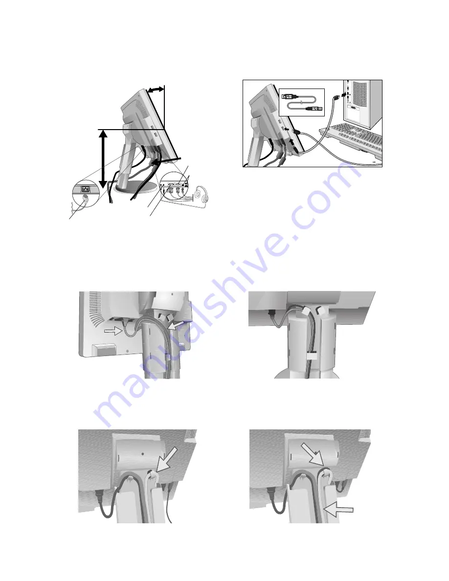
3. Place hands on each side of the monitor to tilt the LCD panel 30-degree angle and lift up to the highest position (

Figure B.1

).

4. Connect all cables to the appropriate connector on the back of the monitor (

Figure B.1

). Using the USB cable, connect the

B type connector to the USB upstream port on the bottom of the monitor and A type connector to the downstream port on
the computer (

Figure C.1

). If you can use the cord from the USB device, use one of the downstream ports on the side or

bottom of the monitor. Connect Headphones (not included) to the appropriate connector at the rear side of the monitor, if
desired (

Figure B.1

).

Input2 (D-Sub)

USB
(LCD205WNXM/LCD225WNXM only)

DVI Cable

Input1 (DVI)

Highest

Stand

Position

Power cord

30° Tilt

A Type

A Type

A Type

B Type

B Type

USB Device

Figure B.1

Figure C.1

Figure C.2

Power cord

DVI Cable

Figure C.3

NOTE:

If connecting both DVI and D-Sub cables, the DVI cable must be connected along side the rib on the power cord
side (

Figure C.2

).

5. For successful cable management, place the cables in this order into the cable management: power cable and DVI cable.

6. Place DVI cable and power cable into the specific hooks as indicated in 

Figure C.3

.

7. Place the D-Sub and the USB cables (LCD205WNXM/LCD225WNXM only) into the specific hooks indicated in 

Figure C.4

.

8. Make sure all cables are resting flat against the stand (

Figure C.4

).

Figure C.4

D-Sub Cable

USB

(LCD205WNXM/

LCD225WNXM only)

Flat

Audio Input

Headphone

Summary of Contents for MultiSync LCD225WNXM

Page 1: ...MultiSync LCD205WNXM MultiSync LCD225WNXM MultiSync LCD225WNX User s Manual...

Page 2: ...rgoDesign is a registered trademark of NEC Display Solutions Ltd in Austria Benelux Denmark France Germany Italy Norway Spain Sweden U K Microsoft and Windows are registered trademarks of the Microsof...

Page 3: ...cause harmful interference to radio communications However there is no guarantee that interference will not occur in a particular installation If this equipment does cause harmful interference to rad...

Page 4: ...with Analog output Connect the 15 pin mini D SUB signal cable to the connector of the display card in your system Figure A 2 Tighten all screws For the MAC Connect the MultiSync Macintosh cable adapt...

Page 5: ...ure B 1 Input2 D Sub USB LCD205WNXM LCD225WNXM only DVI Cable Input1 DVI Highest Stand Position Power cord 30 Tilt A Type A Type A Type B Type B Type USB Device Figure B 1 Figure C 1 Figure C 2 Power...

Page 6: ...ption of these OSD controls NOTE If you have any problem please refer to the Troubleshooting section of this User s Manual Figure D 1 Figure D 2 Figure D 3 Power Cord Figure E 1 Screen Rotation Before...

Page 7: ...ng To prepare the monitor for alternate mounting purposes 1 Place hands on each side of the monitor and lift up to the highest position Remove the cable cover NOTE If you have difficulty removing the...

Page 8: ...ursor goes to left Cursor goes to right At OSD showing Adjustment stage Go to Icon selection stage Adjust value decrease or Cursor for adjust goes to left Adjust value increase or Cursor for adjust go...

Page 9: ...esets 9300 7500 sRGB USER NATIVE select the desired color setting The sRGB and NATIVE color presets are standard and cannot be changed COLOR RED Increase or decreases Red The change will appear on scr...

Page 10: ...l of the monitor INPUT RESOLUTION Analog Input Only Sets of the resolution of input signal to one of the following When vertical active size is 768 you can select resolution from 1024 x 768 1280 x 768...

Page 11: ...sonnel under the following conditions When the power supply cord or plug is damaged If liquid has been spilled or objects have fallen into the monitor If the monitor has been exposed to rain or water...

Page 12: ...ixed patterns on the monitor for long periods of time to avoid image persistence after image effects Get regular eye checkups Ergonomics To realize the maximum ergonomics benefits we recommend the fol...

Page 13: ...0 Hz 1400 x 1050 1 60 Hz to 75 Hz 1440 x 900 1 60 Hz to 75 Hz Recommended resolution is 60 Hz for 1680 x 1050 60 Hz optimal display performance Active Display Area Horizontal 433 4 mm 17 1 inches Vert...

Page 14: ...60 Hz 1400 x 1050 1 60 Hz to 75Hz 1440 x 900 1 60 Hz to 75 Hz Recommended resolution is 60 Hz for 1680 x 1050 60 Hz optimal display performance Active Display Area Horizontal 473 8 mm 18 7 inches Ver...

Page 15: ...to 75Hz 1280 x 1024 1 60 Hz to 75Hz 1360 x 768 1 60 Hz 1400 x 1050 1 60 Hz to 75Hz 1440 x 900 1 60 Hz to 75 Hz Recommended resolution is 60 Hz for 1680 x 1050 60 Hz optimal display performance Active...

Page 16: ...system facilitates setup and installation by allowing the monitor to send its capabilities such as screen size and resolutions supported directly to your computer automatically optimizing display perf...

Page 17: ...y devices NEC DISPLAY SOLUTIONS recommends displaying moving images and using a moving screen saver at regular intervals whenever the screen is idle or turning off the monitor when not in use Image is...

Page 18: ...gy Energy saving mode after a certain time beneficial both for the user and the environment Electrical safety Emissions Electromagnetic fields Noise emissions Ecology The product must be prepared for...

Page 19: ...Japan or http www necdisplay com in USA Energy Saving This monitor features an advanced energy saving capability When a VESA Display Power Management Signalling DPMS Standard signal is sent to the mon...

Reviews: