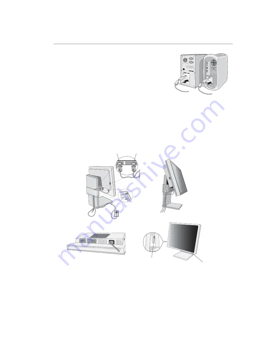
background image

1-6 

English-4

Figure C.1

Figure C.2

Figure D.1

INPUT2

INPUT1

Vacation

Switch

Power Button

Quick Start

To attach the LCD monitor to your system, follow these instructions:

1. Turn off the power to your computer.

2. Connect the DVI signal cable to the connector of the display card in your

system (

Figure A.1

). Tighten all screws.

3. Connect the DVI signal cable to the connector on the back of the monitor

(

Figure C.1

).

NOTE:

Incorrect cable connections may cause irregular operation, damage to
the display and LCD module components and may shorten the lifespan
of the module.

Collect cables and keep them in the stand with attached cable cover. The cable
cover can be attached on the front or back side of Tilt Stand (

Figure C.1, C.2

).

Please check Tilt when you manage cables.

4. Connect one end of the power cord to the AC inlet on the back of the monitor

and the other end to the power outlet (

Figure C.1

).

NOTE:

Please refer to 

Caution

 section (Power Cord Important Information) of this manual for proper selection of AC power

cord.

5. The Vacation Switch on the left side of the monitor must be turned on. Turn on the monitor with the front power button

(

Figure D.1

) and the computer.

NOTE:

The Vacation Switch is a true on/off switch. If this switch is on the OFF position, the monitor cannot be turned on
using the front button. DO NOT switch on/off repeatedly.

NOTE:

If you have any problems, please refer to the 

Troubleshooting

 section of this User’s Manual.

Figure A.1

Summary of Contents for MultiSync LCD2180WG-LED

Page 1: ...1 1 User s Manual SpectraView LCD2180WideGamut LED User s Manual...

Page 2: ...liance Statement English 2 Declaration of Conformity English 2 Contents English 3 Quick Start English 4 Controls English 6 Recommended use English 8 Specifications English 10 Features English 11 Troub...

Page 3: ...your particular country TO PREVENT FIRE OR SHOCK HAZARDS DO NOT EXPOSE THIS UNIT TO RAIN OR MOISTURE ALSO DO NOT USE THIS UNIT S POLARIZED PLUG WITH AN EXTENSION CORD RECEPTACLE OR OTHER OUTLETS UNLES...

Page 4: ...o comply with the limits for a Class B digital device pursuant to part 15 of the FCC Rules These limits are designed to provide reasonable protection against harmful interference in a residential inst...

Page 5: ...eGamut LED monitor with tilt stand Power Cord North America and European Continental Video Signal Cable DVI D to DVI D cable User s Manual CD ROM Cable Cover Remember to save your original box and pac...

Page 6: ...ble cover The cable cover can be attached on the front or back side of Tilt Stand Figure C 1 C 2 Please check Tilt when you manage cables 4 Connect one end of the power cord to the AC inlet on the bac...

Page 7: ...ch stand tighten the four screws NOTE Use only VESA compatible alternative mounting method 100 mm pitch NOTE Handle with care when removing monitor stand NOTE When using the original stand be sure the...

Page 8: ...nta colour Saturation and Hue depending upon which is selected The colour change will appear on screen in the corresponding colours of the displayed image sRGB sRGB mode provides a standard colour spa...

Page 9: ...ly BRIGHTNESS can be adjusted while in the lock out mode OSM LOCK OUT with no control To activate the OSM Lock Out function press SELECT then key and hold down simultaneously To deactivate the OSM Loc...

Page 10: ...he monitor does not operate normally by following operating instructions Do not bend power cord Do not use monitor in hot humid dusty or oily areas If glass is broken handle with care Do not cover ven...

Page 11: ...ize the maximum ergonomics benefits we recommend the following Adjust the Brightness until the background raster disappears Use the preset Size and Position controls with standard signals Use non inte...

Page 12: ...inches Power Supply AC 100 240 V 50 60 Hz Current Rating 1 1 0 5 A Dimensions Landscape 473 mm W x 461 7 mm H x 211 9 mm D 18 6 inches W x 18 2 inches H x 8 3 inches D Weight 18 3 kg 40 3 lbs Environ...

Page 13: ...rity of displayed images Plug and Play The Microsoft solution with the Windows 95 98 2000 Me XP operating system facilitates setup and installation by allowing the monitor to send its capabilities suc...

Page 14: ...ll personal display devices NEC DISPLAY SOLUTIONS recommends displaying moving images and using a moving screen saver at regular intervals whenever the screen is idle or turning off the monitor when n...

Page 15: ...le 2 2 The value is fixed at 2 2 OPTION This setting is recommended for Video source Grey area looks much brighter than NO CORRECTION setting PROGRAMMABLE The brightness of greyscale can be changed to...

Page 16: ...n or up OSM Turn off The OSM control menu will stay on as long as it is in use In the OSM Turn Off submenu you can select how long the monitor waits after the last touch of a button to close the OSM c...

Page 17: ...tion and technical data including the preset timing currently being used and the horizontal and vertical frequencies Increases or decreases the current resolution Press SELECT to move the adjustment m...

Page 18: ...dard signal is sent to the monitor the Energy Saving mode is activated The monitor enters a single Energy Saving mode Mode Power consumption LED colour Normal Operation Approx 100W Green Energy Saving...

Reviews: