background image

English-31

English

NEC DISPLAY SOLUTIONS is strongly committed to environmental protection and sees recycling as one of the company’s 
top priorities in trying to minimize the burden placed on the environment. We are engaged in developing environmentally-
friendly products, and always strive to help defi ne and comply with the latest independent standards from agencies such as 
ISO (International Organisation for Standardization).

Disposing of your old NEC product

The aim of recycling is to gain an environmental benefi t by means of re-use, upgrading, reconditioning or reclamation of 
material. Dedicated recycling sites ensure that environmentally harmful components are properly handled and securely 
disposed. To ensure the best recycling of our products, 

NEC DISPLAY SOLUTIONS offers a variety of recycling procedures


and gives advice on how to handle the product in an environmentally sensitive way, once it has reached the end of its life.

All required information concerning the disposal of the product and country-specifi c information on recycling facilities can be 
found on our following websites:

http://www.nec-display-solutions.com

 (in Europe),

http://www.nec-display.com

 (in Japan) or

http://www.necdisplay.com

 (in USA).

Energy Saving

This monitor features an advanced energy saving capability.

Mode

Power consumption

LED colour

Normal Operation

Approx. 173.5 W

Green (then unlit when 

luminance is stabilized)

Energy Saving Mode

Less than 22 W

Orange

Off Mode

Less than 20.5 W

Unlit

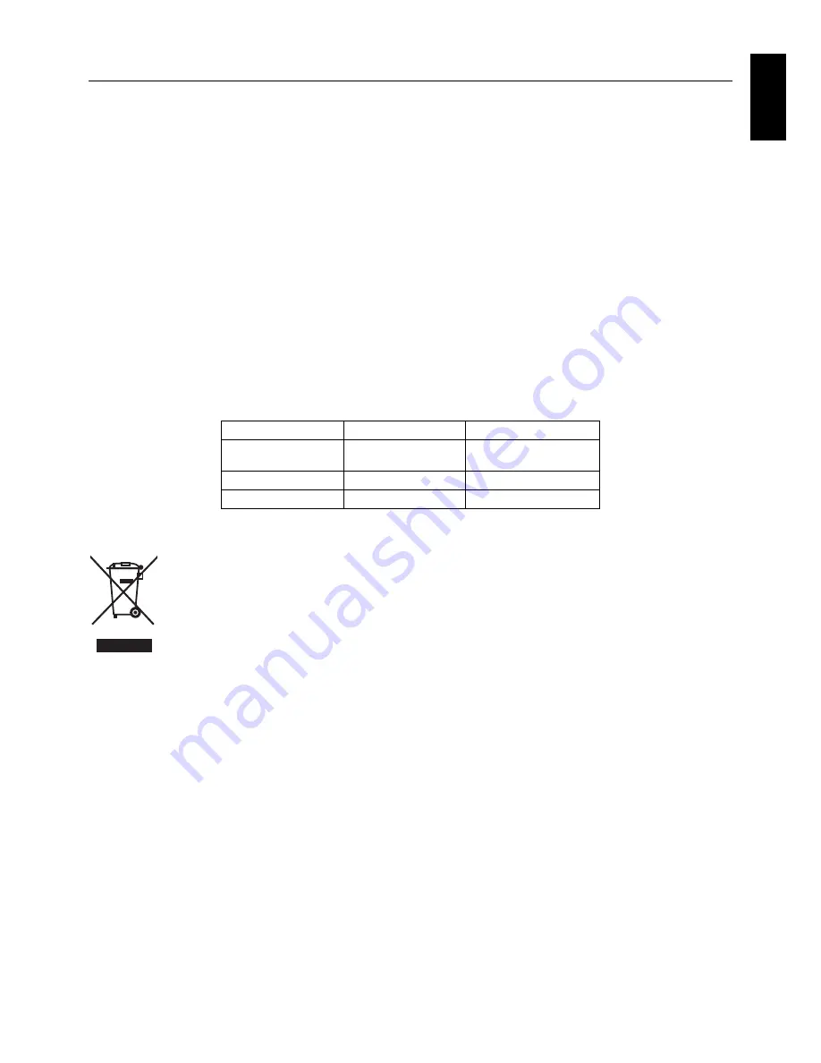
WEEE Mark (European Directive 2012/19/EU)

Within the European Union

EU-wide legislation, as implemented in each Member State, requires that waste electrical and electronic 
products carrying the mark (left) must be disposed of separately from normal household waste. This includes 
monitors and electrical accessories, such as signal cables or power cords. When you need to dispose of your 
NEC display products, please follow the guidance of your local authority, or ask the shop where you purchased 
the product, or if applicable, follow any agreements made between yourself and NEC.

The mark on electrical and electronic products only applies to the current European Union Member States.

Outside the European Union

If you wish to dispose of used electrical and electronic products outside the European Union, please contact your local authority 
so as to comply with the correct disposal method.

Manufacturer’s Recycling and Energy Information

Summary of Contents for MD302C6

Page 1: ...MD302C6 ...

Page 2: ...s and or registered trademarks of Microsoft Corporation in the United States and or other countries VESA is a trademark of the Video Electronics Standard Association All other products and company names are trademarks of their respective owners ...

Page 3: ...English ...

Page 4: ...18 Displaying present state English 18 Performing a DICOM conformance test English 19 Switching the OSD menu English 21 Switching between different EDID content English 21 Changing configurations English 23 Automatic input source detection English 24 Direct OSD setting menu English 25 OSD operation without signal input from computer English 27 Specifications English 28 Troubleshooting English 28 A...

Page 5: ...in Power Off Authentication sign of Standard Inspection Bureau for U S A Complies with ANSI AAMI ES60601 1 2005 A1 2012 CAN CSA C22 2 No 60601 1 08 Windows is a registered trademark of Microsoft Corporation NEC is a registered trademark of NEC Corporation ErgoDesign is a registered trademark of NEC Display Solutions Ltd in Austria Benelux Denmark France Germany Italy Norway Spain Sweden U K Adobe ...

Page 6: ...te the receiving antenna Increase the separation between the equipment and receiver Connect the equipment into an outlet on a circuit different from that to which the receiver is connected Consult your dealer or an experienced radio TV technician for help If necessary the user should contact the dealer or an experienced radio television technician for additional suggestions The user may find the f...

Page 7: ...LET DO NOT REMOVE COVER OR BACK COVER NO USER SERVICEABLE PARTS INSIDE REFER SERVICING TO QUALIFIED SERVICE PERSONNEL CAUTION Power Cord Important Information CAUTION Please use the power cord provided with this display in accordance with the table below If a power cord is not supplied with this equipment please contact your supplier For all other cases please use a power cord that matches the AC ...

Page 8: ...ible EMC Precaution This product requires special EMC precautions and needs to be installed and used according to the following information Use the specified cable Using other cables could increase emission or decrease immunity Do not place any RF communication equipment in the vicinity of this product It could affect the performance of the product Any additional equipment connected to this produc...

Page 9: ...ot cover vent on monitor Vibration can damage the backlight Do not install the monitor where it will be exposed to continual vibration If the monitor s LCD panel is broken do not come in contact with the liquid crystal and handle with care To prevent damage to the LCD monitor caused by tipping over due to earthquakes or other shocks make sure to install the monitor in a stable location and take me...

Page 10: ...eyes periodically by focusing on an object at least 6 m 20 feet away Blink often Position the monitor at a 90 angle to windows and other light sources to minimize glare and reflections Adjust the monitor tilt so that ceiling lights do not reflect on your screen Position whatever you are looking at most of the time the screen or reference material directly in front of you to minimize turning your h...

Page 11: ... D to DVI D cable 1 x 2 DisplayPort cable x 2 Power Cord 2 Quick Reference Guide USB Cable Remember to save your original box and packing material to transport or ship the monitor 1 Dual link DVI cable 2 Type and number of power cords included will depend on the where the LCD monitor is to be shipped When more than one power cord is included please use a power cord that matches the AC voltage of t...

Page 12: ...end to the power outlet NOTE Please refer to the CAUTION section of this Installation Maintenance Guide for proper selection of AC power cord 4 Turn on the display and the computer Make sure that the main power switch on the back side of the display is turned on Back of the display Computer To the wall outlet DisplayPort cable or DVI cable 5 To keep the cables neatly organized place them into the ...

Page 13: ...ecommended as it may cause a frame skip In addition mixed connection of different signal types DVI DisplayPort may result in slight differences of luminance and color between left and right screen depending on the display controller models used in the two computers Note This configuration is not supported by the NEC GammaCompMD QA calibration software Two 3MP screens from 1 computer Two 3MP screen...

Page 14: ...erly The supplied USB cable can also be used for the followings To calibrate the display To calibrate multiple displays in succession To calibrate the display Connect the supplied USB cable between one of the display s USB upstream port and the computer s USB 2 0 downstream port Regarding display calibration please refer to the GammaCompMD QA user manual To calibrate multiple displays in successio...

Page 15: ...h the OSD screen displayed press this button to move the cursor to right left or up down MENU button Without displaying the OSD on the screen press this button to switch the input port displayed on the screen The input port is switched in the following order INPUT 1 INPUT 2 and Input 1 Input 2 This function is available only when ENABLE FUNCTIONS setting of the direct OSD menu setting is set to En...

Page 16: ...lied DisplayPort cable INPUT2 of DVI 2 Digital video signal input port Connect the supplied DVI cable USB upstream port When connecting an USB device to USB downstream port connect one end of the supplied USB cable to the display s USB upstream port and the other end to an USB 2 0 port of the computer USB downstream port x2 An USB device with a maximum current consumption of 500mA per port can be ...

Page 17: ...VI There are two input ports INPUT 1 and INPUT 2 See the following table and figure for the difference between input port and input source Input port Input Source Input 1 DisplayPort 1 DVI 1 Input 2 DisplayPort 2 DVI 2 INPUT 1 DisplayPort 1 DVI 1 INPUT 2 DisplayPort 2 DVI 2 Input ports are located on the side of the display Without displaying the OSD on the screen press the MENU button to switch t...

Page 18: ...ns INPUT 1 INPUT 2 INPUT 1 INPUT 2 Input source switching Input source of each input port of INPUT 1 and INPUT 2 can be switched Input port Input Source Input 1 DisplayPort 1 DVI 1 Input 2 DisplayPort 2 DVI 2 This operation is available only when ENABLE FUNCTIONS of the direct OSD menu setting is set to Enable Switching Input Source or Enable Both Functions The procedure to switch input source dep...

Page 19: ...with different input sources DVI DisplayPort is not recommended for standard applications It may result in slight differences of luminance and color between left and right screen and or a frame skip See page 9 When Concurrent Mode is selected for INPUT SOURCE BUTTON MODE Concurrent Mode allows simultaneous switching of the input source of INPUT 1 and INPUT 2 Press either the plus or the minus butt...

Page 20: ...ee page 18 Present state see page 18 DICOM conformance test see page 19 Menu selection see page 21 Exit Full Menu Information see page 18 Present state see page 18 Switching EDID see page 21 Menu selection see page 21 Exit Switching configuration see page 23 Input source auto scanning see page 24 DICOM conformance test see page 19 Direct OSD setting menu see page 25 NOTE The OSD menu contents may ...

Page 21: ...guration CONFIG 1 Configuration 1 400 cd m2 DICOM GSDF Clear Base CONFIG 2 Configuration 2 400 cd m2 DICOM GSDF 6500K CONFIG 3 Configuration 3 300 cd m2 DICOM GSDF 6500K INPUT SOURCE AUTO SCANNING Automatic switching setting of input signal Disable Does not switch input signal automatically Enable Switches input signal automatically DIRECT OSD SETTING MENU Direct OSD menu setting ENABLE FUNCTIONS ...

Page 22: ...ation EDID data state Total operating hours Maintenance information NOTE The OSD menu disappears in 15 seconds Displaying present state The present operating state and setting of the display can be checked by selecting from the OSD menu 1 Displaying the OSD main menu Press and hold the MENU button for 2 seconds The OSD menu appears Press either or button to move the cursor and select PRESENT STATE...

Page 23: ...try OSD operation method without actual OSD screen on page 27 DICOM conformance test procedure 1 Checking the gamma setting Follow the instructions Displaying present state on page 18 and make sure that the gamma correction is set to DICOM GSDF PRESENT STATE Gamma correction setting 2 Displaying the OSD main menu Press and hold the MENU button for 2 seconds The OSD menu appears Press either or but...

Page 24: ...ply with AAPM TG18 guidelines for primary displays Canceled Test has been cancelled Passed When Passed or Failed is followed by the test has not been performed under the recommended condition minimum 60 minutes of active backlight time or the luminance is unstable Failed LUMINANCE Explanation Stable Luminance is stable Unstable Luminance is unstable NOTE If the test is repeated within 30 seconds U...

Page 25: ...n to store the OSD selected main menu MENU SELECTION Reference menu Full menu NOTE The OSD menu disappears in 15 seconds Switching between different EDID content EDID stands for Extended Display Identification Data which among other information reports the display s resolution capabilities to the computer s operating system With the Switching EDID function of the Full Menu OSD two different displa...

Page 26: ... EDID Explanation 6MP 3MP x2 Full pixel mode using the complete area of the LCD panel The display is used with a resolution of either 3280 x 2048 or 2x 1640 x 2048 1 screen display with native resolution 2 screen display with 1640 x 2048 1640 x 2048 display 1640 x 2048 display 6MP 3MPx2 QXGA based mode for backward compatibility with original 3MP displays The display is used with a resolution of e...

Page 27: ...ng Configuration number Luminance cd m2 Gamma Maximum Minimum Ambient 1 400 0 8 0 0 DICOM GSDF 2 400 0 8 0 0 DICOM GSDF 3 300 0 8 0 0 DICOM GSDF Configuration switching 1 Displaying the OSD main menu Press and hold the MENU button for 2 seconds The OSD main menu appears Press either or button to move the cursor and select SWITCHING CONFIGURATION Switching Configuration 2 Switching between configur...

Page 28: ... selectable as follows Automatic scanning setting 1 Displaying the OSD main menu Press and hold the MENU button for 2 seconds The OSD main menu appears Press either or button to move the cursor and select INPUT SOURCE AUTO SCANNING Input Source Auto Scanning 2 Changing the input signal scanning function Press the MENU button and the INPUT SOURCE AUTO SCANNING submenu appears INPUT SOURCE AUTO SCAN...

Page 29: ... OSD SETTING MENU Direct OSD Setting Menu 2 Direct OSD setting menu Press the MENU button and the DIRECT OSD SETTING MENU submenu appears DIRECT OSD SETTING MENU Press either or button to move the cursor and select ENABLE FUNCTIONS Direct OSD Setting Menu Explanation ENABLE FUNCTIONS Sets the selected function to be enabled INPUT SOURCE BUTTON MODE Selects switching mode of an input signal EXIT Cl...

Page 30: ...s the MENU button and return to the Direct OSD Setting Menu in step 2 NOTE The OSD menu disappears in 15 seconds Selecting switching mode of an input signal 1 Displaying the OSD main menu Press and hold the MENU button for 2 seconds The OSD main menu appears Press either or button to move the cursor and select DIRECT OSD SETTING MENU Direct OSD Setting Menu 2 Direct OSD setting menu Press the MENU...

Page 31: ...D main menu 1 While the display is in energy saving mode the LED indicator is orange press and hold MENU for 2 seconds LED indicator 2 The LED indicator next to the power switch turns to green the display is turned on and is temporarily in the normal operation mode for up to 3 hours At the same time the OSD main menu appears Reference Menu Full Menu 3 The OSD operation without signal input from co...

Page 32: ...g 38 8 lbs 27 4 x 19 2 24 3 x 11 9 inches W x H x D Safety certifications ANSI AAMI ES60601 1 2005 A1 2012 CAN CSA C22 2 No 60601 1 08 FCC B ICES 003 B CE MDD VCCI B FDA510 K 1 billion 109 NOTE Technical specifications are subject to change without notice MD302C6 is intended to be used in rooms with less than 50 to 69 7 lx ambient light The maximum ambient light level depends on technical QA stand...

Page 33: ...ickness If the screws are too long they could damage the internal parts If they are too short the connection becomes loose and the display could fall out Mounting plate thickness Screw size 1 5 3 5 mm ISO M4 x 12 CAUTION How to attach an arm stand 1 Place a soft cloth or cushioning material over a stable even surface 2 Put the display face down on the soft cloth 3 Remove 4 screws and detach the ti...

Page 34: ...ity slot for use with the MicroSaver Security Lock System by Kensington Technology Group The MicroSaver locks are available at PC supply stores Note Kensington is the registered trademark of Kensington Technology Group DOWN UP DVI 2 DisplayPort DVI 1 DisplayPort POWER AC IN ...

Page 35: ...http www nec display solutions com in Europe http www nec display com in Japan or http www necdisplay com in USA Energy Saving This monitor features an advanced energy saving capability Mode Power consumption LED colour Normal Operation Approx 173 5 W Green then unlit when luminance is stabilized Energy Saving Mode Less than 22 W Orange Off Mode Less than 20 5 W Unlit WEEE Mark European Directive ...

Page 36: ...isplay Solutions of America 500 Park Blvd Suite 1100 Itasca Illinois 60143 USA Phone 1 630 467 3000 Fax 1 630 467 3010 NEC Display Solutions Europe GmbH Landshuter Allee 12 14 D 80637 Muenchen Germany Phone 49 0 89 99699 0 Fax 49 0 89 99699 500 Vol 1 1st Edition June 2014 ...

Reviews: