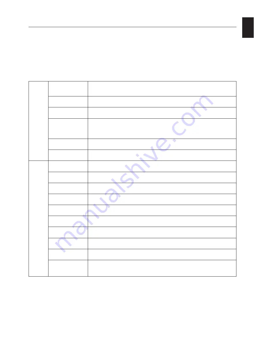
background image

English-15

English

Tag1

Luminance

Adjusts the overall image and screen background luminance.
Press “Left” or “Right” to adjust.
When LUMINANCE is adjusting, a numerical value blinks.

Auto Contrast

Adjusts the image displayed for non-standard video inputs. Press “SELECT” to adjust.

(Analog input only)

Any adjustment requires the image to have white portions.

Auto Black Level

Automatically adjusts the black level. Any adjustment requires the image to have black

(Analog input only)

portions. Press “SELECT” to activate Auto Adjust.

AMBIENT LIGHT

Luminance setting depends on ambient light compensation.

COMP.

OFF: No ambient light compensation.
1: Compensation only active during calibrations.
2: Compensation always active.

Black Level main

Allows you to manually adjust the black level. Press “Left” or “Right” to adjust.

(Analog input only)

Black Level R/G/B

Allows you to manually adjust the R/G/B black with independent controls.

(Analog input only)

Tag2

R-H.position

Adjusts the position of the red component of the image. Press “Left” or “Right” to adjust.

(Analog input only)

G-H.position

Adjusts the position of the green component of the image. Press “Left” or “Right” to adjust.

(Analog input only)

B-H.position

Adjusts the position of the blue component of the image. Press “Left” or “Right” to adjust.

(Analog input only)

R-FINE

Adjusts the “FINE” setting of the RED component of the image.

(Analog input only)

Press “Left” or “Right” to adjust.

G-FINE

Adjusts the “FINE” setting of the GREEN component of the image.

(Analog input only)

Press “Left” or “Right” to adjust.

B-FINE

Adjusts the “FINE” setting of the BLUE component of the image.

(Analog input only)

Press “Left” or “Right” to adjust.

R-SHARPNESS

Adjusts the sharpness of the red component of the image. Press “Left” or “Right” to adjust.

(Analog input only)

G-SHARPNESS

Adjusts the sharpness of the green component of the image.

(Analog input only)

Press “Left” or “Right” to adjust.

B-SHARPNESS

Adjusts the sharpness of the blue component of the image.

(Analog input only)

Press “Left” or “Right” to adjust.

DVI Long Cable

Compensates for image degradation caused by using a long DVI cable.

(Digital input only)

There are 4 possible settings, with “0” being the lowest level of compensation and
“3” being the highest level. The default setting is “1”.

Advanced OSD

<How to use the advanced menu>

When OSD is off, push the “RESET” and “EXIT” button at the same time.

You will see the Advanced menu.
This menu is larger than the normal OSD.

<How to exit the advanced menu>

Push the “EXIT” button.

To make an adjustment, ensure that the tag is highlighted, then press “SELECT”.

To move to another tag, press “EXIT”, then press “Left” or “Right” to highlight another tag.

Summary of Contents for MD213MC - MultiSync - 21.3" LCD Monitor

Page 1: ...MD212MC MD213MC MD213MG INSTALLATION MAINTENANCE GUIDE...

Page 2: ...ions Ltd in Austria Benelux Denmark France Germany Italy Norway Spain Sweden U K All other brands and product names are trademarks or registered trademarks of their respective owners This symbol warns...

Page 3: ...atient environment and IEC 60601 1 certified equipment inside the patient environment Equipment connected to the analog or digital interfaces must comply with the respective IEC standards e g IEC 6095...

Page 4: ...a particular installation If this equipment does cause harmful interference to radio or television reception which can be determined by turning the equipment off and on the user is encouraged to try t...

Page 5: ...let and refer servicing to qualified service personnel under the following conditions When the power supply cord or plug is damaged If liquid has been spilled or objects have fallen into the monitor I...

Page 6: ...wered on This feature can be turned on or off in the Advanced OSD In case you find such bright Brand Logo annoying in your reading room environment you may easily switch this off By keeping the EXIT b...

Page 7: ...DVI D to DVI D cable 1 Quick Reference Guide CD ROM x 2 Cable Cover Power Cord Type of power cord included will depend on the where the LCD monitor is to be shipped Quick Reference Guide DVI D to DVI...

Page 8: ...mode Refer to the Screen rotation section in this manual 4 Place hands on each side of the monitor to tilt the LCD panel to a 30 angle and lift up to the highest position Figure C 1 5 Connect all cab...

Page 9: ...0 Turn on the monitor with power switch on the top Portrait or left side Landscape of the monitor Figure E 1 Turn on the computer NOTE DO NOT switch on off repeatedly 11 No touch auto adjust automatic...

Page 10: ...f the monitor and lift up to the highest position Figure RL 1 To rotate screen place hands on each side of the monitor screen and turn clockwise from Landscape to Portrait or counter clockwise from Po...

Page 11: ...the flexible arm for detailed instructions To fulfill the safety requirements the monitor must be mounted to an arm which guaranties the necessary stability under consideration of the weight of the m...

Page 12: ...tton for at least 3 seconds to display the visual inspection grayscale drawing and check the display performance Enters the OSD Control menu Enters OSD sub menus Changes the input source when not in t...

Page 13: ...SIZE H SIZE Analog input only Adjust the horizontal size by increasing or decreasing this setting If the AUTO Adjust function do not give you a satisfactory picture setting a further tuning can be per...

Page 14: ...LUE BASE Color temperature setting for Blue Base x ray film simulation NOTE To reset a poor image setting turn on the monitor by using the power switch on the top in portrait mode or left side in land...

Page 15: ...eset choices are 10 120 seconds by 5 second increments OSD LOCK OUT This control completely locks out access to all OSD control functions When attempting to activate OSD controls while in the Lock Out...

Page 16: ...lution other than the optimized resolution is used After power is turned on or when there is a change of input signal or the video signal doesn t have proper resolution the Resolution Notifier window...

Page 17: ...he blue component of the image Press Left or Right to adjust Analog input only R FINE Adjusts the FINE setting of the RED component of the image Analog input only Press Left or Right to adjust G FINE...

Page 18: ...ot clock For this a Moir test pattern could be used This function may alter the width of the picture Use left Right Menu to center the image on the screen If the V Size H Size is wrongly calibrated th...

Page 19: ...ted when CUSTOM is selected PRIORITY only for MD212MC MD213MC Sets gamma characteristics for optimum viewing of contrast or color GRAYSCALE Optimizes gamma for contrast COLOR Optimizes gamma for color...

Page 20: ...nput signal is lost STANDARD Monitor enters power save mode automatically when the input signal is lost Response Improve Turns the RESPONSE IMPROVE function on or off Response Improve may reduce blurr...

Page 21: ...in the corner of the screen Signal information is either On Off Resolution Notifier The optimal resolution is 1200 x 1600 in portrait mode or 1600 x 1200 in landscape mode for MD212MC and 1536 x 2048...

Page 22: ...ker than normal or have color distortion Use of the Clamp position control will adjust images to their normal state TagA CALIBRATION Selects the Calibration mode page 21 SELF TEST MODE Displays an all...

Page 23: ...ontamination DO NOT press the calibrator against the display panel KEY MAP UP DOWN Changes from setting to setting LEFT RIGHT Changes the setting selection ie SELF or COPY SELECT Moves to the next ste...

Page 24: ...y A must display a white screen Enter the Advanced OSD by pressing RESET and EXIT Use LEFT and RIGHT keys to move into Tag A and select SELF TEST MODE 2 Select COPY in the Mode selection in Display B...

Page 25: ...UNING MODE 1 1 MD213MG does not have FINE TUNING MODE 10 At the FINE TUNING MODE message Figure 13 press SELECT if the calibration is satisfactory If the calibration is unsatisfactory there are two op...

Page 26: ...17 3 Select the Color setting in COLOR 2 selection and Gamma setting in GAMMA selection 2 MD213MG does not have COLOR selection 4 Press SELECT to start the DICOM MEASUREMENT This may take several min...

Page 27: ...o 75 Hz NEC DISPLAY SOLUTIONS cites 1440 x 900 1 at 60 Hz to 75 Hz recommended resolution for optimal 1600 x 1200 1 at 60 Hz display performance Active Landscape Horiz 432 mm 17 0 inches Vert 324 mm 1...

Page 28: ...x 1200 1 at 60 Hz Analog 1920 x 1200 1 at 60 Hz Digital NEC DISPLAY SOLUTIONS cites 2048 x 1536 1 at 35 Hz recommended resolution for optimal 2048 x 1536 at 60 Hz Digital display performance Active La...

Page 29: ...at 75Hz 1280 x 960 1 at 60 Hz 1280 x 1024 1 at 60 Hz to 85 Hz 1600 x 1200 1 at 60 Hz 1920 x 1200 1 at 60 Hz Analog 1920 x 1200 1 at 60 Hz Digital NEC DISPLAY SOLUTIONS cites 2048 x 1536 1 at 35 Hz rec...

Page 30: ...djust the colors on your screen and customise the color accuracy of your monitor to a variety of standards OSD On Screen Display Controls Allow you to quickly and easily adjust all elements of your sc...

Page 31: ...or shows rough images only Image is displayed only roughly pixels are missing and OSD warning OUT OF RANGE is displayed Either signal clock or resolution is too high Choose one of the supported modes...

Page 32: ...in Japan or http www necdisplay com in USA Energy Saving This monitor features an advanced energy saving capability When a VESA Display Power Management Signalling DPMS Standard signal is sent to the...

Reviews: