background image

English-26

Copy Calibration

The luminance can be copied from one display to one or more additional displays. Using this feature reduces the variation 
between different displays allowing them to match each other more closely.
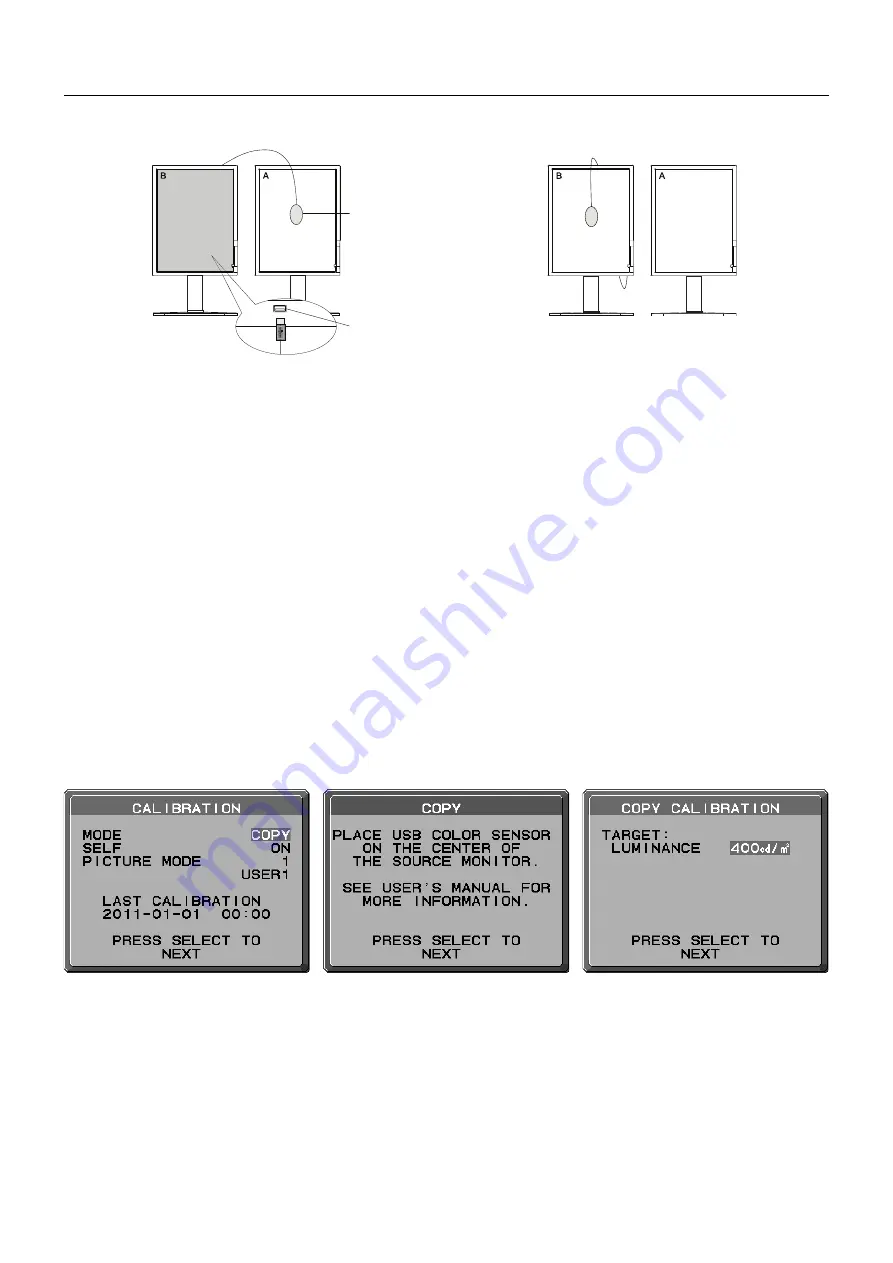
USB optical sensor

Figure C.1

Display A

 – SOURCE display of luminance to copy.

Display


B

 – MD211G3 which performs a copy.

Figure C.2

Sensor Port 
(located at the back of the monitor)

1.  To show the CALIBRATION menu, plug-in the USB optical sensor to the sensor port (

Figure C.1

) or select the STAND 

ALONE CALIBRATION in the advanced menu (page 20).

2.  Set the target white color on Display A. For example, enter the Advanced OSD by pressing RESET and EXIT.

3.  Using “LEFT” or “RIGHT” of Display B, select COPY in the MODE selection 

(Figure C.3)

.

4.  Select ON or OFF in the SELF selection. If ON selected, SELF Calibration execute with COPY Calibration. Select the target 

PICTURE MODE. Please select the same target PICTURE MODE as Display A. Press SELECT to go to the next section.

5.  The procedure will ask for the USB optical sensor to be placed on the center of the display panel 

(Figure C.4)

. Tilt the 

display panel approximately 5° backward and place the USB optical sensor in the center of the display panel 

(Figure C.1)

.

NOTE:


Place the USB optical sensor fl at against the display A to avoid any infl uence of ambient light. 

Do not 

press the USB 

optical sensor against the display panel. Press “SELECT”.

6.   Press SELECT on Display B to start measuring the luminance of Display A.

7.  After copying Display A information, the target luminance will be stored and displayed in the OSD of Display B. The target 

value is not adjustable (

Figure C.5

).

8.   Remove the USB optical sensor from source Display A and place in the center of Display B (

Figure C.2

).

9.   Press SELECT to start the copy calibration. Copy calibration may take several minutes depending on the user settings.

10. Once the calibration is successfully completed, the luminance of Display A and Display B should match. If ON is selected in 

the SELF section, Self Calibration is automatically executed.

11. After completing the calibration, you can set DATE and TIME using control keys.

Figure C.4

Figure C.5

Figure C.3

Summary of Contents for MD211G3-R

Page 1: ...Medical Display MD211G3 INSTALLATION MAINTENANCE GUIDE...

Page 2: ...nit This symbol alerts the user that important literature concerning the operation and maintenance of this unit has been included Therefore it should be read carefully in order to avoid any problems P...

Page 3: ...REFER SERVICING TO QUALIFIED SERVICE PERSONNEL CAUTION Power Cord Important Information CAUTION Please use the power cord provided with this monitor in accordance with the table below If a power cord...

Page 4: ...ms is not recommended if cleaning of the air intakes from dust and textile lint in regular time intervals cannot be performed by the user maximum interval six months This device is equipped with an in...

Page 5: ...at interference will not occur in a particular installation If this equipment does cause harmful interference to radio or television reception which can be determined by turning the equipment off and...

Page 6: ...ot install where the monitor will be exposed to continual vibration If monitor or glass is broken do not come in contact with the liquid crystal and handle with care To prevent damage to the LCD monit...

Page 7: ...optimum performance allow 30 minutes for the monitor to warm up Adjust the monitor height so that the top of the screen is at or slightly below eye level Your eyes should look slightly downward when...

Page 8: ...DisplayPort cable CD ROM x 2 Power Cord 2 Quick Reference Guide USB Cable Remember to save your original box and packing material to transport or ship the monitor 1 Dual link DVI cable 2 Type and num...

Page 9: ...nnect the DisplayPort cable to the connector of the display controller in your system Figure A 2 Figure A 1 Figure A 2 DisplayPort cable NOTE 1 Please use a DisplayPort cable with a DisplayPort logo 2...

Page 10: ...sub monitors can be daisy chained Figure C 1 Highest Stand Position Power cord 30 Tilt Figure C 1a A Type B Type A Type B Type Sensor Port 1 DVI D Cable DisplayPort Cable USB Upstream Port USB Downst...

Page 11: ...switch on the top Portrait or left side Landscape of the monitor Figure E 1 Turn on the computer NOTE If you have any problems please refer to the Troubleshooting section of this Manual Figure E 1 Po...

Page 12: ...screen place hands on each side of the monitor and turn clockwise from Landscape to Portrait or counter clockwise from Portrait to Landscape Figure R 1 To rotate the OSD menu between landscape and por...

Page 13: ...down on a desk or table with the front sensor situated off the edge Figure S 2 5 Slide the cable cover up NOTE The cable cover is not removable 6 Place hand on the back side of the monitor and lift up...

Page 14: ...xits any OSD sub menu Exits the OSD Control menu Shows OSD menu Shows PICTURE MODE Selects the item Changes the input source Resets the OSD back to factory settings Shows the quick screen QA test patt...

Page 15: ...URE MODE Change to a picture mode which is most suitable for the type of content that is shown You can choose one of two possible PICTURE MODES See Advanced OSD menu Tag1 PICTURE MODE page 17 and Usin...

Page 16: ...tor will automatically return to normal mode QA TEST Provides a quick daily visual image quality check of this diagnostic monitor by just using a button on the monitor MENU Tools LANGUAGE The OSD cont...

Page 17: ...ves a warning when there is no Horizontal or Vertical Sync After power is turned on or when there is a change of input signal the No Signal message window will appear OUT OF RANGE This function gives...

Page 18: ...F ERROR result in is a quick indicator of the gray level quality against the ideal DICOM curve Depending on the QA standard which is used in your country different GSDF error limits may exist Please c...

Page 19: ...m by a monitor Gamma is defined by the relationship between the signal input voltage and the resulting intensity of the monitor s light output A perfect linear device would have a Gamma of 1 0 A Gamma...

Page 20: ...RIGHT to select FIRST When current video input signal is not present then the monitor searches for a video signal from a different video source If a video signal is supplied by the other video source...

Page 21: ...a screen will appear indicating the OSD controls are locked out There are three types of OSD LOCK OUT OSD LOCK OUT with no control To activate the OSD Lock Out function press SELECT then RIGHT button...

Page 22: ...y a sensor LANDSCAPE The preferred timing is fixed to landscape orientation 2048x1536 pixels PORTRAIT The preferred timing is fixed to portrait orientation 1536x2048 pixels Note If you have any proble...

Page 23: ...l display performance Active Display Area Landscape Horiz Vert Portrait Horiz Vert 433 2 mm 17 1 inches 324 9 mm 12 8 inches 324 9 mm 12 8 inches 433 2 mm 17 1 inches USB Hub I F Port Load Current USB...

Page 24: ...resolutions supported directly to your computer automatically optimizing display performance Intelligent Power Manager System Provides innovative power saving methods that allow the monitor to switch...

Page 25: ...mage NOTE As with all personal display devices NEC DISPLAY SOLUTIONS recommends using a moving screen saver at regular intervals whenever the screen is idle or turning off the monitor when not in use...

Page 26: ...pear on screen Figure A 1 When Stand Alone Calibration is executed the message window will appear Figure A 3 and the screen becomes dark for about 10 seconds Then ZERO CALIBRATION will start automatic...

Page 27: ...S 3 Press SELECT to go to the next section To select AUTO CALIB go to step 6 To select EXPERT CALIB go to step 7 AUTO CALIB Make sure that the USB optical sensor is connected to the sensor port 6 The...

Page 28: ...n 5 The procedure will ask for the USB optical sensor to be placed on the center of the display panel Figure C 4 Tilt the display panel approximately 5 backward and place the USB optical sensor in the...

Page 29: ...the advanced menu page 24 2 Select GAMMA ADJUST in the MODE selection Figure 1 3 Select the target UNIFORMITY Press SELECT to go to the next section 4 Set the target LUMINANCE cd m2 Figure 2 Press SEL...

Page 30: ...setting is 1 or 2 Please perform AMBIENT SENSOR CALIBRATION in the following cases The usage environment has changed AMBIENT SENSOR CALIBRATION requires an illuminance meter and a telescopic luminanc...

Page 31: ...aving measured press SELECT without changing the value 6 After the CALIBRATION SUCCEEDED message appears Figure AS 4 press SELECT You can set DATE and TIME by using control keys and press SELECT 7 To...

Page 32: ...t Signalling DPMS Standard signal is sent to the monitor the Energy Saving mode is activated The monitor enters a single Energy Saving mode Mode Power consumption LED colour Normal Operation Approx 10...

Reviews: