background image

J-i

J-i

J-i

はじめに

このたびは、iS8-2K(以降「iS8-2K本体」を「本機」または「プロジェクタ」と呼びます)をお買い上げいただき
誠にありがとうございます。
本機を安全に正しく使用していただくため、ご使用の前に、この取扱説明書(本書)をよくお読みください。
取扱説明書は、いつでも見られる所に大切に保存してください。万一ご使用中にわからないことや不具合が
生じたときにお読みください。

この装置は、情報処理装置等電波障害自主規制協議会(VCCI)の基準に基づくクラスA情報技術装置
です。
この装置を家庭環境で使用すると電波妨害を引き起こすことがあります。この場合には使用者が適切な
対策を講ずるよう要求されることがあります。

■本機を安全にお使いいただくために、ご使用の前に必ずお読みください■

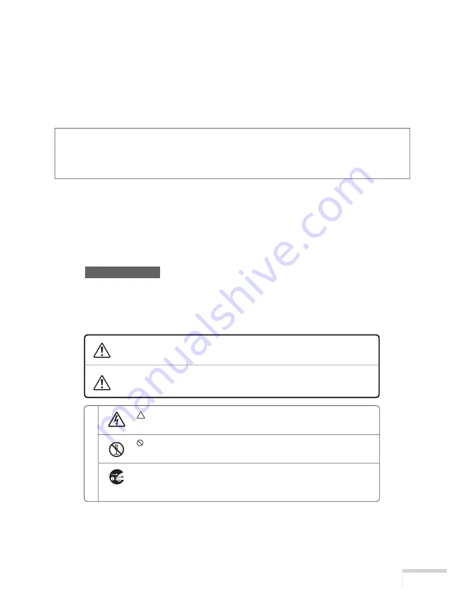
  絵表示について

この取扱説明書および製品への表示では、製品を安全に正しくお使いいただき、あなたや
他の人々への危害や財産への損害を未然に防止するために、いろいろな絵表示をしていま
す。その表示と意味は次のようになっています。
内容をよく理解してから本文をお読みください。

この表示を無視して、誤った取り扱いをすると、人が死亡や大け
がをするなど人身事故の原因となります。

この表示を無視して、誤った取り扱いをすると、人がけがをした
り周囲の家財に損害をあたえたりすることがあります。

注意

 記号は注意(警告を含む)をうながすことを表しています。

図の中に具体的な注意内容(左図の場合は感電注意)が描かれています。

 記号はしてはいけないことを表しています。

図の中に具体的な禁止内容(左図の場合は分解禁止)が描かれています。

● 記号はしなければならないことを表しています。
図の中に具体的な指示内容(左図の場合は電源プラグをコンセントから抜く)
が描かれています。

警告

Summary of Contents for iS8-2K

Page 1: ...iS8 2K DIGITAL PROJECTION CINEMA User s Manual DIGITAL PROJECTION INTERNATIONAL and NEC Viewtechnology Ltd ...

Page 2: ... Interference Causing Equipment Regulations Precautions Please read this manual carefully before using your iS8 2K and keep the manual handy for future reference WARNING This is a Class A product In a domestic envi ronment this product may cause radio interfer ence in which case the user may be required to take adequate measures CAUTION In order to reduce any interference with ra dio and televisio...

Page 3: ... building codes d Please consult your dealer for more in formation e Do not attempt to stack projectors on the ceiling Power Supply 1 The projector is designed to operate on a power supply of 2 8 KW AC200 240V 50 60Hz Ensure that your power supply fits this requirement before attempting to use your projector 2 Consult your dealer for installing the power cord to the projector DO NOT install the po...

Page 4: ...eat emitted from the light output CAUTION High Pressure Lamp May Explode if Improperly Handled Refer Servicing to Quali fied Service Personnel Lamp Caution Please read before operation Due to the lamp being sealed in a pressurized environment there is a small risk of explosion if not operated correctly There is minimal risk involved if the unit is in proper working order but if damaged or operated...

Page 5: ... brochure accompagnant l appareil DOC avis de conformité Cet appareil numérique de la classe A respecte toutes les exigences du Réglement sur le Matériel D interférence du Canada Recommandations importantes Ces instructions de sécurité ont pour but d assurer une longue vie à votre projecteur et d éviter un incendie ou une décharge électrique Prière de les lire attentivement et de tenir compte de t...

Page 6: ...ise d alimentation en courant pendant un orage Cela pourrait causer un choc électrique Nettoyage 1 Débrancher le projecteur avant de le nettoyer 2 Nettoyer régulièrement le boîtier extérieur avec un chiffon humide S il est trés sale utiliser un détergent doux Ne jamais utiliser de détergent forts ou de solvants tels que de l alcool ou du diluant 3 Utiliser un souffleur ou du papier pour objectif p...

Page 7: ...Warning lorsque les 750 heures la vie la plus courte de fonctionnement sont atteintes Lorsque ce message apparaît priére de contacter votre revendeur pour un remplacement Si la lampe explose de la fumée peut étre produite par les fentes d aération situées sur l arrière de l appareil Cette fumée est composée de verre sous forme de particules et de gaz de Xenon et n est pas nuisible si elle est main...

Page 8: ...SES BEFINDEN SICH KEINE FÜR DIE BEDIENUNG DES GERÄTES ER FORDERLICHENTEILE LASSEN SIE DEN KUNDENDIENST NUR VON HIERFÜR QUALIFIZIERTEN PERSONEN DURCH FÜHREN DIESES SYMBOL WARNT DEN BEDIENER DASS INNERHALB DES GERÄTES UNISOLIERTE TEILE VORHANDEN SIND DIE HOCHSPANNUNG FÜHREN UND DEREN BERÜHRUNG EINEN ELEKTRISCHEN SCHLAG VERURSACHEN KANN DIESES SYMBOL MACHT DEN BËDIENER DARAUF AUFMERK SAM DASS WICHTIG...

Page 9: ...rojektor wurde für eine Netzspannung von 2 8KW 200 240 V Wechselstrom 50 60 Hz konzipiert Stellen Sie sicher dass die vorhandene Spannungsversorgung diesen Vorgaben entspricht bevor Sie versuchen Ihren Projektor zu betreiben 2 Zum Installieren des Netzkabels am Pro jektor wenden Sie sich bitte an Ihren Fach händler UNTER KEINEN UMSTÄNDEN versuchen das Netzkabel selbst zu install ieren Brand und Sc...

Page 10: ...unsachgemäßer Handhabung kann die Hochdrucklampe explodieren Überlassen Sie die Reparatur ausschließlich qualifiziertem Servicepersonal Vorsichtsmaßnahmen bezüglich der Lampe Bitte vor dem Betrieb durchlesen Aufgrund der unter Druck luftdicht verschloss enen Lampe besteht bei falscher Handhabung eine geringe Explosionsgefahr Wenn sich das Gerät in einwandfreiem Zustand befindet ist dieses Risiko m...

Page 11: ...用者が適切な 対策を講ずるよう要求されることがあります 本機を安全にお使いいただくために ご使用の前に必ずお読みください 絵表示について この取扱説明書および製品への表示では 製品を安全に正しくお使いいただき あなたや 他の人々への危害や財産への損害を未然に防止するために いろいろな絵表示をしていま す その表示と意味は次のようになっています 内容をよく理解してから本文をお読みください この表示を無視して 誤った取り扱いをすると 人が死亡や大け がをするなど人身事故の原因となります この表示を無視して 誤った取り扱いをすると 人がけがをした り周囲の家財に損害をあたえたりすることがあります 注意 記号は注意 警告を含む をうながすことを表しています 図の中に具体的な注意内容 左図の場合は感電注意 が描かれています 記号はしてはいけないことを表しています 図の中に具体的な禁止内容 左図の場合...

Page 12: ...げたり ねじったり 引っ張っ たりしない コードを加熱しない 電源コードが傷んだら 芯線の露出 断線など 販 売店に交換をご依頼ください 故障したときは電源プラグを抜く 煙が出ている 変なにおいや音がする場合やプロ ジェクタを落したり キャビネットを破損した場 合は 本体の電源を切り 電源プラグをコンセン トから抜いてください 火災 感電の原因となり ます 販売店へ修理をご依頼ください 水場や水にぬれるような所には置かない 次のような水にぬれるようなおそれがある所では 使用しないでください またプロジェクタの上に 水の入った容器を置かないでください 火災 感 電の原因となります 雨天や降雪中 海岸や水辺で使用しない 風呂やシャワー室で使用しない プロジェクタの上に花びん 植木鉢を置かない プロジェクタの上にコップ 化粧品 薬品を置 かない 万一プロジェクタの内部に水などが入った場合 は ま...

Page 13: ... ら抜いて販売店にご連絡ください キャビネットは絶対にあけない プロジェクタのキャビネットを外したり あけた りしないでください また改造しないでくださ い 火災 感電の原因となります 内部の点検 調整 修理は販売店にご相談くださ い ランプカバーは外さない プロジェクタの内部には高圧ランプがあります 破裂のおそれがありますので サービスマン以外 はランプカバーを外さないでください 警告 分解禁止 雷が鳴りだしたら 電源プラグに触れない 雷が鳴りだしたら 電源プラグに触れないでくだ さい 感電の原因となります プロジェクタのレンズをのぞかない プロジェクタのレンズをのぞかないでください 動作中は強い光が投写されていますので 目を痛 める原因となります 特にお子様にはご注意くだ さい レンズをのぞかない 異物挿入禁止 ...

Page 14: ... ふた の部分が高温になり溶けることがあります 動作中にレンズの前に金魚鉢 凸レンズ 虫眼鏡 などを置かないでください 火災の原因となるこ とがあります 移動するときは電源コードを抜く 移動させる場合は 電源を切り必ず電源プラグを コンセントから抜き 機器間の接続ケーブルを外 したことを確認のうえ 行ってください 移動するときはキャリングハンドルを持つ プロジェクタを移動するときは4人以上で行って ください 必ずキャリングハンドルを持ってください レン ズやアナモフィックレンズ用の3本のシャフトを 持つと 落としたりしてけがの原因となることが あります 長期間使用しないときは 電源プラグを抜く 長期間 プロジェクタをご使用にならないときは 安全のため必ず電源プラグをコンセントから抜い てください お手入れの際は電源コードを抜く お手入れの際は 安全のため電源プラグをコンセ ントから抜いてく...

Page 15: ...J v J v J v 点検 工事について 1年に一度くらいは内部の掃除を販売店などにご 相談ください プロジェクタの内部にほこりがた まったまま 長い間掃除をしないと火災や故障の 原因となることがあります 特に湿気の多くなる梅雨期の前に行うと より効 果的です なお 内部の掃除費用につきましては 販売店などにご相談ください 内部の掃除を販売店で 注意 ...

Page 16: ...りますので レンズ面には手をふ れないでください また 本機を使用されないときは 添付のレンズ キャップをかぶせておいてください 廃棄について 本体廃棄の際は お買い上げの販売店にお問い合 わせください ランプ取り扱い上の注意 プロジェクタの光源には 内部圧力の高いランプ を使用しています ランプは 衝撃やキズ 使用時間の経過による劣 化などにより 大きな音をともなって破裂した り 不点灯状態となることがあります また ラ ンプが破裂や不点灯に至るまでの時間 条件に は ランプの個体差や使用条件によって差があ り 本書に記してある指定の使用時間内であって も 破裂または不点灯状態に至ることがありま す 光源に使われているランプの使用時間が750時間 最短時 を超えると 液晶画面に L a m p Warning と表示されます このメッセージが表 示された場合には すみやかに販売店にランプ...

Page 17: ...d 16 3 Projection of Images Basic Operation 17 3 1 Steps of projecting images 17 3 2 Step 1 Turning your projector on 17 3 3 Step 2 Selecting the title of input signal 19 3 4 Step 3 Adjusting the position and size of projected screen 20 3 5 Step 4 Turning your projector off 21 4 Using Menus 23 4 1 Basic operation with adjustment menus 23 4 2 Table of adjustment menus 26 4 3 Source Select 29 4 4 Se...

Page 18: ... screen Also the lens memory function allows storage of the zoom position and lens shift position according to the size of each picture 䢇 Up to date functions of DLP CinemaTM available This projector supports CineLinkTM CineCanvasTM CinePalletteTM and CineBlackTM which are the new functions for security subtitles etc developed by Texas Instruments Incorporated 1 CineLinkTM Security management This...

Page 19: ...ote cable wired DVI D signal cable Ferrite clamp core for HDSDI signal cable User s Manual CompactFlash Memory card 16MB with Adapter Anamorphic lens mount with two shafts Foot x4 NOTE Should any of the items delivered to you in the package be missing or damaged please contact your dealer distributor from whom you have purchased your projector immediately with the information ...

Page 20: ...g handles when carrying your projector There are a total of two carrying handles a set of bottom ones on the front and the back of your projector CAUTION Be sure to carry the projector using a minimum of four people When moving the projector do not use any parts other than the carrying handles Otherwise the projector may tumble or drop causing personal injury 䢇 Lens sold separately Images are proj...

Page 21: ...e to be connected here See page 8 䡵 Rear of the projector 䢇 Air outlet The heat of the lamp is vented here CAUTION Do not touch the air outlet when your projector is operating Otherwise the high temperature may cause burns 䢇 Air inlet Air is taken in here to provide cooling of the projector CAUTION Do not cover the air inlet and outlet during operation Inadequate air intake may lead to a rise in i...

Page 22: ...for fine adjustment of the size of projected image See page 21 4 LENS SHIFT buttons Press these buttons while depressing the CTL button to move the projected image down up left or right See page 20 5 MENU button Press this button and menus for various settings and adjustments will be displayed See page 23 6 SELECT buttons Press the SELECT button when a menu is displayed and a menu item can be sele...

Page 23: ...y the power to your projector When turning on the power to the projector first set the main power switch to ON thereby setting the projector in a standby state See page 17 12 POWER indicator 13 STATUS indicator 14 BACKLIGHT switch Operate this switch to turn on the back light of the LCD screen 15 LCD CONTRAST Adjustment Dial Use this dial to adjust the contrast of the LCD screen Green lighting Whe...

Page 24: ...he projector to the PC 3 Remote control terminal REMOTE 1 Connect the remote control of the projector using the supplied remote control cable NOTE You cannot operate the remote control of your projector unless it is connected by the remote control cable 4 PC control terminal PC CONTROL Mini D Sub 9P Use this terminal when controlling your projector in serial connection from a PC Use a commercially...

Page 25: ... terminal SDI B BNC Connect a Video Server or Video source to this terminal Use a 75Ω coaxial cable 8 HDSDI A input terminal SDI A BNC Connect a Video Server or Video source to this terminal Use a 75Ω coaxial cable 9 DVI D A input terminal DVI A DVI D 24P Connect the DVI D output terminal of a PC to this terminal Use a commercially available DVI D signal cable 10 DVI D B input terminal DVI B DVI D...

Page 26: ... this terminal when setting data on the projector Use a commercially available RS 232C straight cable to connect the projector to a personal computer PC 13 Ethernet port LAN1 LAN2 RJ 45 Use this port when controlling your projector in LAN connection from a PC Use a commercially available LAN cable 10Base T 100Base T to connect the projector to the PC ...

Page 27: ...ON which puts your projector on standby See page 17 2 POWER OFF button Operate this button to turn off standby the power to your projector Press it two seconds or longer 3 Numeric buttons 1 to 0 buttons Use these buttons to enter alphanumeric characters See page 25 4 TEST button Press this button and a test pattern will be displayed 5 KEYSTONE button Press the KEYSTONE R button while depressing th...

Page 28: ...lection function If you want to the menu item number see page 26 28 9 POSITION button Press the POSITION LENS button while depressing the CTL button to make lens shift adjustment See page 20 10 PICTURE MUTE button Press this button to turn off image projection temporarily Press it again and the image will be projected again Press the PICTURE MUTE SHUTTER button while depressing the CTL button then...

Page 29: ... Press the FOCUS button while depressing the CTL button to make lens focus adjustment See page 20 18 ZOOM Ⳮ ⴑ button Press the ZOOM button while depressing the CTL button to make lens zoom adjustment See page 20 19 CTL button The CTL button is a shift function used to access alternative functions on other buttons NOTE The following buttons cannot be used with this projector WHITE BAL ADJUST PICTUR...

Page 30: ...See page 16 2 2 Connecting the image input terminals Your projector has four image input terminals namely the HDSDIAinput terminal the HDSDI B input terminal the DVI D A input terminal and the DVI D B input terminal HDSDI A B input terminal SDI A SDI B Inputs serial digital images from a Video Server or Video source DVI D A B input terminal DVI A DVI B Inputs digital RGB signals from a PC Informat...

Page 31: ...ng the various control terminals For control your projector comes with such ports as the USB ports type A type B the PC control terminal and the Ethernet port RJ 45 USB port Type A USB A For future extension USB port Type B USB B Use this port when controlling the projector in USB connection from a PC PC control terminal PC CONTROL Use this terminal when controlling the projector in serial connect...

Page 32: ...our projec tor Be sure to ground the equipment to ensure safety To avoid electric shocks request a professional to carry out the grounding Be sure to perform earth connection before inserting the power plug into the wall outlet NOTE In the following instances do not disconnect the power plug from the outlet Otherwise trouble may occur When the fan is running for about three minutes after the power...

Page 33: ...is OFF when you connect the power cord to an AC outlet or discon nect the power cord from it Connection or disconnection of the power cord with the main power switch ON may cause projector trouble Be sure to turn your projector on or off in two steps of operation with the main power switch and the POWER button POWER ON OFF button on the remote control 䢇 Turning power on See page 18 1 Set the main ...

Page 34: ...ns cap removed from the lens Otherwise the lens cap may get deformed due to a heat buildup In the following instances the power to your projector cannot be turned on even if you press the POWER button When the inside temperature is abnormally high The protective function prevents power from turning on Wait some time until the projector inside cools down and then turn on the power When the lamp is ...

Page 35: ... the display will cycle as Source Select Setup information 4 Press the SELECT button The title of input signal is displayed When you have made a wrong selection press the SELECT button Areturn will be made to the previous menu 5 Press the SELECT button to display the title of the signal to be projected on the LCD screen 6 Press the ENTER button The title of the signal to be projected is selected T...

Page 36: ...rn name on the liquid crystal display switches 3 Display on the liquid crystal display the name of the test pattern to be projected then press the ENTER button To cancel the test pattern display select a different signal to be projected 䡵 Adjusting the position of projected screen Lens shift 1 Press the LENS SHIFT buttons while depressing the CTL button on the control panel of your projector as re...

Page 37: ... screen Focus 1 Press the FOCUS buttons while depressing the CTL button on the control panel of your projector as required When controlling with the remote control press the FOCUS button while depressing the CTL button 3 5 Step 4 Turning your projector off 1 Press the POWER button on the control panel of your projector two seconds or longer The power is turned off and the POWER indicator switches ...

Page 38: ...your projector goes out and the main power supply is turned off NOTE In the following instances do not turn off the main power switch or pull out the power plug from the outlet Otherwise your equipment may develop trouble When the fan is running for about three minutes after the power is turned off ...

Page 39: ...reen 2 Select Information by pressing the SELECT button At each press of the SELECT button the display will cycle as Source Select Setup Information 3 Press the SELECT button The submenu Lamp Time of Information is displayed The menu item can be selected by pressing the ENTER button instead of the SELECT button To return to the previous state press the SELECT button or the CANCEL button 4 Select t...

Page 40: ...menu Firmware by pressing the SELECT button At each press of the SELECT button the display will cycle as BIOS Firmware Data 7 Press the SELECT button A Firmware version is displayed 8 Press the SELECT button A return is made to the menu one rank up 9 Press the SELECT button A return is made to the menu still another rank up ...

Page 41: ...low To delete a character during entry press the SELECT button while depressing the CTL button Example of Entry To enter XGA for instance use the following procedure 1 Press the 8 button three times V W X 2 Press the SELECT button 3 Press the 3 button XG 4 Press the SELECT button 5 Press the 1 button XGA Numeric buttons Numeric Press directly While depressing CTL button button 1 A B C 1 a b c 2 D ...

Page 42: ...le Select Test Pattern Setup File Name TCGD File Select File Name 000 003 084 034 085 086 033 050 051 052 032 048 049 002 008 007 027 029 028 026 030 031 087 088 089 006 012 Create PCF Create SOURCE SOURCE Name Input Aspect Ratio 1 0 1 25 1 33 1 42 1 5 1 78 1 85 2 35 067 Position H Position V Image Input Size H 4096 4095 4096 4095 0 65535 068 069 070 PCF Name Input ImageInputSize V 0 65535 071 Cre...

Page 43: ...ol Disable Enable 038 044 043 040 039 024 037 005 083 022 042 041 096 095 094 DVI Dual Twin DVI B MMS 2 MMS 1 MMS 1 Dual 091 093 092 File Name 045 screen file1 screen file3 File Name 046 047 Signal Config Signal Port Select Title Name001 Title Name100 Data File Select MCGD File select PCF File select Screen File Select 011 0 1 0 009 013 025 SOURCE File Select File Name File Name File Name File Nam...

Page 44: ... 018 074 075 076 077 078 079 080 081 082 3 100 Adjust Auto TEST Pattern OFF Alignment Convergence H Ramp RGB Black RGB Blue RGB Green RGB Red RGB White Y Color Bars YCbCr Blue YCbCr Green YCbCr Red YCbCr White RGB CROSS RGB 50 White 035 016 004 Title Name001 Title Name100 MCGD Name Input I J M K L 001 NOTE The number at the left side of each menu item is a number of a Direct menu selection functio...

Page 45: ...uto Adjustment is made automatically 䢇 Lamp Auto The initial setting for auto adjustment of lamp brightness is made 䢇 Image Orient Make a selection according to the setup position of your projector and screen WARNING Please request your dealer distributor to set up your projector Never carry out the setup by yourself A fall or other accidents may occur to cause injury Desktop Front The projector i...

Page 46: ...iling Front The projector body is installed upside down and projection is made from front of the screen 䢇 Create MCGD This is a function for adjusting chromaticity by inputting optical characteristics for your projector Please request your dealer distributor to perform the setting 䢇 Shutter Mode The lens shutter function will be activated during the switching of signals Please request your dealer ...

Page 47: ...input signal 䢇 Title Select Set an input terminal and various modes for the saved title Signal Port Select Select an input terminal Signal Config Please request your dealer distributor to make this setting Data File Select Select PCF File MCGD File or Screen File 䢇 Title Make The title of input signal is saved Up to 14 alphanumeric characters can be entered Up to a hundred titles can be saved in y...

Page 48: ...ector are locked to disable Enable Enable a lock on the control buttons on your projector Disable Disable the lock on the control buttons Keep pressing the CANCEL button 10 seconds or longer and menu operation can be performed by temporarily disabling the lock on the control buttons 4 5 Information Lamp time version information error codes etc are displayed 䡵 Lamp Time Elapsed time of the lamp in ...

Page 49: ...ur projector is displayed 䢇 Data The Data version for your projector is displayed 䡵 Error Code When an error occurs the error code is displayed Please see the Appendix for error codes 䡵 IPAddress Displays the IP address set in your projector 䡵 MMS Status Indicates the status of the MMS 1000 connected to the iS8 2K ...

Page 50: ...y deteriorate or peel off When removing dust on the ventilation opening suck it off using an adapter with a brush on a vacuum cleaner Never allow the cleaner without an adapter to come in direct contact or use a nozzle adapter in cleaning Clean the ventilation opening at regular intervals Dust if allowed to accumulate there may cause heating inside which leads to functional trouble The interval wh...

Page 51: ...ce of Your Projector 5 2 Cleaning the lens Clean the lens the same way as with camera lens using a commercially available camera blower or cleaning paper for glasses Take care not to damage the lens in the cleaning ...

Page 52: ...er inside temperature is abnormal 9 Set Temp Temperature set inside temperature is abnormal 10 DLP PS Engine power is abnormal 11 DLP Comm TI Engine communication error is detected 12 Lamp Timer R Lamp Timer read error is detected 13 Interlock Fail Inter Lock error is detected 14 No Support Eng DVI Dual Engine does not support 15 Lamp Timer W Lamp Timer write error is detected 20 System Fail 21 Se...

Page 53: ... IB Flash Protect Fail 47 IB GPI Macro Fail 48 IB A D Macro Fail 60 PB Diag Not Performed 61 PB FPGA Code Invalid 62 PB FPGA INITZ Fail 63 PB McBSP XRDY Fail 64 PB FPGA Done Fail 65 PB FPGA Reg R W Fail 66 PB Serial ID Chip Fail 67 PB CLUT SRAM Fail 68 PB OvFS SDRAM Fail 69 PB Resizer FIR Fail 70 PB Resizer FIFO Fail 71 PB Other Fail ...

Page 54: ... selected Check to see if the cable is properly connected to the input terminal Check to see whether the lens shutter is closed Check to see if the settings are all adjusted properly The image is distorted Check to see if the projector is properly set up Thex image is blurred Make certain that the lens is properly focused Check to see if the screen and the projector are installed at correct angles...

Page 55: ...mplete before engaging in browser operations Operation with a browser that uses a proxy server may not be possible depending on the type of proxy server and the setting method Although the type of proxy server will be a factor it is possible that items that have actually been set will not be displayed depending on the effectiveness of the cache and the contents set from the browser may not be re f...

Page 56: ...Shifts the projected screen leftward Shifts the projected screen rightward Stops the shifting Shifting can also be stopped by clicking or once again during the shifting Zoom Zooms up the lens Zooms down the lens Stops the zooming Zooming can also be stopped by clicking or once again during the zoom up down Focus Focuses up the lens Focuses down the lens Stops the focusing Focusing can also be stop...

Page 57: ...nch Projector Status This displays the condition of the projector Remaining Lamp Time Displays the remaining life of the lamp as a percentage Projector Usage Displays how many hours the projector has been used Lamp Hour Meter Displays how many hours the lamp has been used Error Status Displays the status of errors occurring within the projector Refresh Updates the display of the following conditio...

Page 58: ...ormity 80 edge to center Contrast Ratio More than 1000 1 Full On Off More than 400 1 ANSI Lens Movement Motorized Horizontal and Vertical Lens Shift Motorized Zoom and Focus Built in Lens Shutter Electrical Inputs Digital I O RGB DIGITAL 2 DVI D 24pin TMDS specification SDI 2 BNC SMPTE 292M Level C 4 2 2 PC Card 1 PCMCIA Data Back up External Control RS232C 1 D sub 9 pin Remote Control wired Ether...

Page 59: ...0 to 35 C Humidity 20 80 non condensing Storage Temperature 4 to 140 F 20 to 60 C Humidity 20 80 non condensing Regulations Safety EMC USA UL60950 FCC part15 Class A Canada CSA60950 ICES 003 Class A Europe EN60950 EN55022 Class A EN55024 EN61000 3 2 EN61000 3 3 Oceania EN60950 AS NZS CISPR 22 2002 Class A Asia EN60950 CISPR 22 1 Permissible deviation for RGB convergence Pixel deviation is 1 2 pixe...

Page 60: ...000 1 Marche arrêt à fond Plus de 400 1 ANSI Commande de l objectif Commande du mouvement horizontal et vertical de l objectif à moteur Commande du zoom et de la mise au point à moteur Obturateur d objectif incorporé Partie électrique Entrées E S numérique RGB NUMERIQUE 2 DVI D 24fiches Spécifications TMDS SDI 2 BNC SMPTE 292M Niveau C 4 2 2 Sauvegarde des données par carte PCMCIA PC 1 Commande ex...

Page 61: ...e magasinage 20 à 60 C Humidité 20 80 sans condensation Réglements applicables Sécurité EMC USA UL60950 FCC partie15 Classe A Canada CSA60950 ICES 003 Classe A Europe EN60950 EN55022 Classe A EN61000 3 2 EN61000 3 3 Océanie EN60950 AS NZS CISPR 22 2002 Classe A Asie EN60950 CISPR 22 1 La déviation admissible pour la convergence RGB déviation de pixel est de 1 2 pixel ou moins au centre et de 3 4 p...

Page 62: ...ßigkeit 80 Kante zu Mitte Kontrastverhältnis Mehr als 1000 1 Voll Ein Aus Mehr als 400 1 ANSI Linsenbewegung Servo in Horizontal und Vertikalrichtung Motorzoom und fokus Integrierter Linsenverschluss Elektrik Eingänge Digital I O RGB DIGITAL 2 DVI D 24 pol TMDS Spezifikation SDI 2 BNC SMPTE 292M Level C 4 2 2 PC Karte 1 PCMCIA Daten Backup Externe Steuerung RS232C 1 D sub 9 pol Fernbedienung Kabel...

Page 63: ...erungstemperatur 20 C bis 60 C Feuchtigkeit 20 80 ohne Kondensatbildung Verordnungen Sicherheit EMC USA UL60950 FCC Abschnitt 15 Klasse A Kanada CSA60950 ICES 003 Klasse A Europa EN60950 EN55022 Klasse A EN55024 EN61000 3 2 EN61000 3 3 Ozeanien EN60950 AS NZS CISPR 22 2002 Klasse A Asien EN60950 CISPR 22 1 Die zulässigeAbweichung für RGB Konvergenz Bildpunktabweichung beträgt max 1 2 Pixel in der ...

Page 64: ...フォーミティ 80 中心から周囲 コントラスト比 1000 1以上 Full On Off 400 1以上 ANSI レンズ調整機能 電動レンズシフト 縦 横 電動ズーム 電動フォーカス レンズシャッター 電気 信号入力端子 RGB DIGITAL 2 DVI D 24pin TMDS specification SDI 2 BNC SMPTE 292M Level C 4 2 2 PCカードスロット 1 PCMCIA Data Back up 外部コントロール RS232C 1 D sub 9 pin リモコン端子 Ethernetポート RJ 45 USBポート タイプB 電源 AC 200 240V 50 60Hz 定格入力電流 14 A ...

Page 65: ... 外形寸法 600mm 幅 x 872mm 奥行 x 687mm 高さ レンズフードを含む 前後のキャリングハンドルを除く 質量 約94Kg レンズを除く 使用環境 動作温度 10 35 C 動作湿度 20 80 ただし結露しないこと 保存温度 20 60 C 保存湿度 20 80 ただし結露しないこと 規格 1 RGBのコンバーゼンス 画素ズレ は 打上角度0度の場合 センター 1 2画素以下 周辺 3 4画素以下です アナモフィックレンズの場合を除く 2 参考値 この仕様 意匠はお断りなく変更することがあります ...

Page 66: ... Feet 4 Ferrite clamp core 15 Firmware 33 Focus 7 13 20 G GPIO Control 31 H HDSDI A input terminal SDI A 9 HDSDI B input terminal SDI B 9 I Image Orient 29 Information 32 IP Address 33 L Lamp Auto 29 Lamp Hour Meter 32 Lamp setup 29 Lamp Time 32 LCD screen 6 Lens 4 Lens shift 6 12 20 M Main power switch 4 O ON OFF Timer 32 P Panel Key Lock 32 PC card slot 9 PC control terminal PC CONTROL 8 PC cont...

Page 67: ...51 T Test Pattern Setup 32 Title Delete 31 Title Make 31 Title Select 31 Title Setup 31 U USB port USB A 8 USB port USB B 8 V Version 32 Z Zoom 6 13 21 ...

Page 68: ... NEC Viewtechnology Ltd 2004 Printed in Japan Ver 1 5 04 ...

Page 69: ...7N8Pxxxx ...

Reviews: