CHAPTER 6 CAUTIONS
User’s Manual U11595EJ5V0UM
48
6.6
Port 4, Port 5
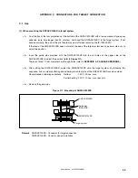
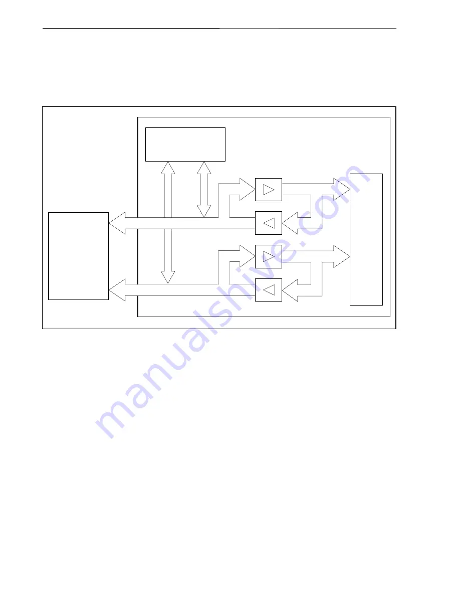
The connection of VHCT541 and VHC541 to Port 4 and Port 5 is as shown below.
Figure 6-2. Circuit Diagram of Port 4, Port 5
IE-703002-MC
Emulation CPU
Port 4
Port 5
Target system
VHCT541
VHC541
VHC541
VHCT541
Emulation
RAM
When the IE-703002-MC is used for developing application systems using V850/Sxx products by connecting an
option board, apply the settings specified in the user’s manual of the option board used.


