background image

18


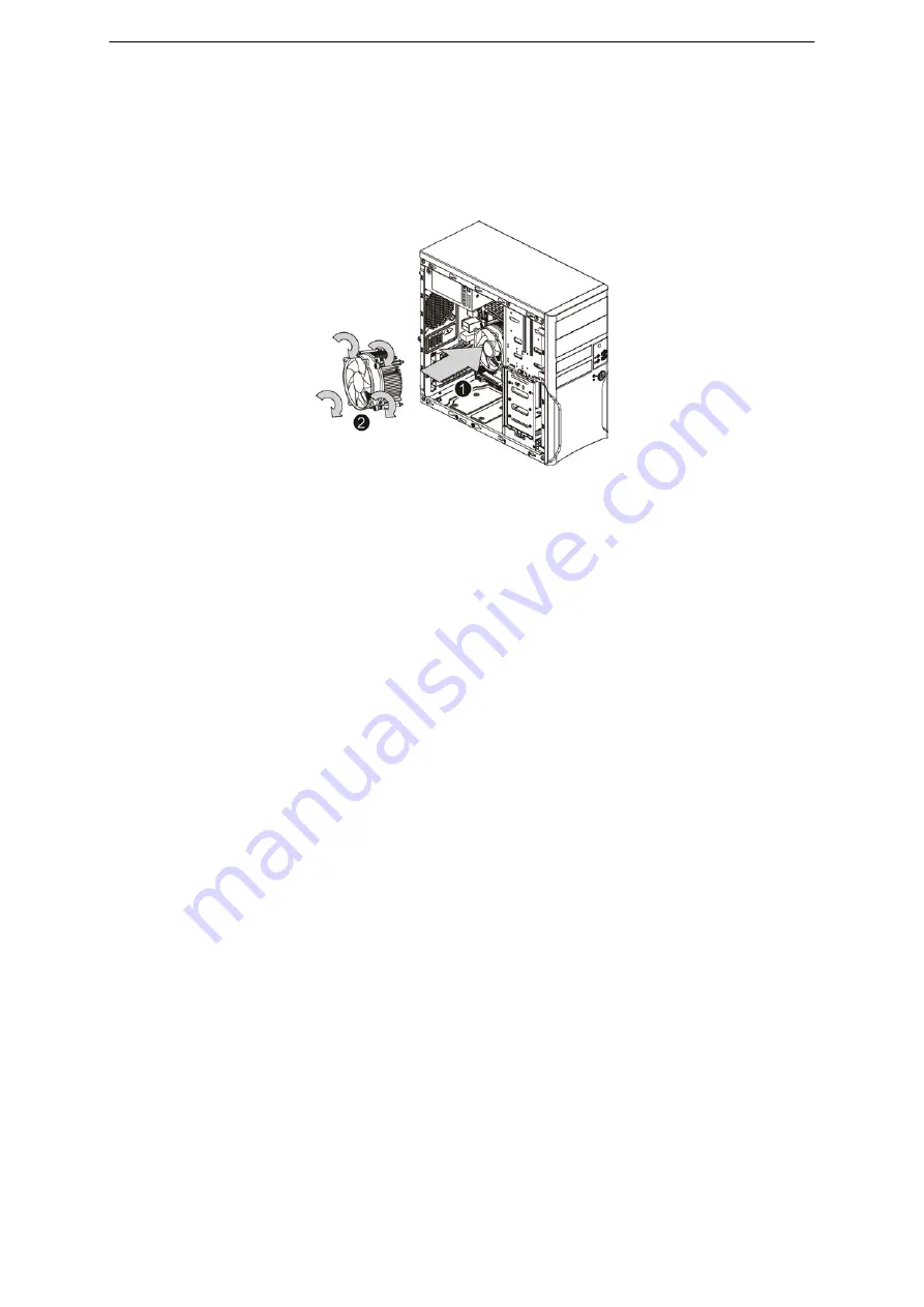
Cooling Fan Installation / Removal 


1. 

Disconnect the processor cooling fan cable from motherboard. 


2. 

Use a long-nosed screwdriver to loosen the four cooling fan mounting pins. 


3. 

Lift the cooling fan away from the motherboard. 


4. 

Lay down the cooling fan in an upright position - with the thermal patch facing upward. Do not let the 
thermal patch touch the work surface. 


Summary of Contents for Express5800/T71h

Page 1: ...NEC Express5800 T71h User s Guide ...

Page 2: ...pdates made on NEC Express5800 T71h service guide Date Chapter Updates Copyright Copyright 2016 by NEC Incorporated All rights reserved No part of this publication may be reproduced transmitted transcribed stored in a retrieval system or translated into any language or computer language in any form or by any means electronic mechanical magnetic optical chemical manual or otherwise without the prio...

Page 3: ... bits and pieces of additional information related to the current topic WARNING Alerts you to any damage that might result from doing or not doing specific actions CAUTION Gives precautionary measures to avoid possible hardware or software problems IMPORTANT Reminds you to do specific actions relevant to the accomplishment of procedures ...

Page 4: ... of the device To prevent electrostatic damage Avoid hand contact by transporting and storing products in static safe containers Keep electrostatic sensitive parts in their containers until they arrive at static free workstations Place parts on a grounded surface before removing them from their containers Avoid touching pins leads or circuitry Always be properly grounded when touching a static sen...

Page 5: ... server in this manner results in improper airflow and improper cooling that can lead to thermal damage Danger of explosion if battery is incorrectly replaced Replace only with the same or equivalent type recommended by the manufacturer Dispose of used batteries according to the manufacturer s instructions ...

Page 6: ...mful interference to radio communications Operation of this equipment in a residential area is likely to cause harmful interference in which case the user will be required to correct the interference at his own expense CE Statement This is a Class A product In domestic environment this product may cause radio interference in which case the user may be required to take adequate measures EN55022 NEC...

Page 7: ...GS AND CAUTIONS III REGULATORY NOTICES V TABLE OF CONTENTS VI SYSTEM COMPONENTS 1 SYSTEM SPECIFICATIONS 2 Hardware specification 2 Environmental specification 4 Mechanical specification 5 Power supply specification 6 APPEARANCE OF SYSTEM 7 Front view 7 Rear view 8 Internal Component 9 Switch and LED Indicators Introduction 10 Front Panel LED Description 10 LAN Port LED Description 11 ...

Page 8: ...l 19 PCI Expansion Card Installation Removal 20 Install the expansion card 20 How to set up RAID with Intel Software RAID RSTe 21 Configuring a RAID array in RAID BIOS 22 Hard Disk Drive Installation Removal 26 HDD Installation Sequence 27 CABLE ROUTING 67 Cable Routing image 67 TROUBLESHOOTING 68 Error Symptoms List 68 BIOS BEEP CODES 71 BIOS Beep Codes Table 71 PEI Beep Codes 71 BIOS Recovery In...

Page 9: ...1 System components Item Description 1 Front Bezel door 2 Power supply 3 Cooling fan 4 System side cover 5 Motherboard 6 Hard disk drive cage ...

Page 10: ...s x8 slot running at x4 PCIE_2 PCI Express x16 slot running at x16 Memory Four DDR4 2133Hz slots ECC modules supported UDIMM supported up to 16GB per module Support maximum 64GB I O Ports Front Panel Two USB 3 0 Ports Rear Panel One VGA Port Two USB 3 0 Ports Two USB 2 0 Ports One 1000BASE T LAN Port Three Audio connectors Internal I O Five SATA ports One USB 2 0 Type A port Status LED indicators ...

Page 11: ...e DIMM non interleaving DIMM_P0_A0 or DIMM_P0_B0 Two DIMM interleaving DIMM_P0_A0 DIMM_P0_B0 Four DIMM full memory configuration DIMM specifications Size Speed Type 8GB 16GB 2133 MHz DDR4 ECC DIMM Processor General processor specifications Items Description Manufacturing Technology 14 nm Thermal Design Power Max 80W Socket Type LGA1151 ...

Page 12: ...ssure level in idle mode on bystander position 34 dBA Sound pressure level in operating mode on bystander position 39 dBA All temperature ratings shown are for sea level An altitude derating of 1 XC per 300 m 1 8 XF per 1 000 ft to 3048 m 10 000 ft is applicable No direct sunlight allowed Storage maximum humidity of 95 is based on a maximum temperature of 45 XC 113 XF Altitude maximum for storage ...

Page 13: ...TX Micro Advanced Technology Extended System board dimensions Length Width 244mm 244mm System Dimensions Height Depth Width 360 00mm 386 00mm 175 00mm Server weight maximum configuration approximate Fully loaded configuration including the keyboard mouse and kits 12 5KG ...

Page 14: ...pproximate 1 483 kg 3 26 lb Input requirements Rated input voltage Normal line voltage 100 240 VAC 115 VAC 230 VAC Line frequency 47 63 Hz Rated input current Load 10A 100 127Vac 60Hz Load 5A 220 240Vac 50Hz Inrush current No damage Power supply output power Rated steady state power Maximum peak power 500W 500W Operating conditions Temperature Humidity non condensing 5 50 C 41 122 F Up to 85 relat...

Page 15: ...nce of System Front view Item Icon Component Description 1 USB 3 0 connectors Connects to USB devices 2 Power button Press the button to power on system 3 HDD LED indicator Indicates the HDD access health status ...

Page 16: ... devices 4 USB 3 0 connectors Connects to USB devices 5 Gigabit LAN port Connects to an Internet or intranet network 6 Audio connectors Connects this audio jack for line in devices Connects this audio jack for a headphone or 2 channel speaker Connects this audio jack for microphones 7 PCIe slot covers Remove the cover to install PCIe card 8 System fan Regulates the system airflow ...

Page 17: ...9 Internal Component Item LED indicator 1 HDD cages 2 Power module bay 3 Cooling fan assemblies 4 PCI slot bracket 5 Motherboard ...

Page 18: ...rs located on the Front panel LAN port Knowing what each LED indicator signifies can aid in problem diagnosis and troubleshooting Front Panel LED Description Number LED Color Status Description 1 Power Green Solid On System is powered on 2 HDD Activity Amber Blink HDD access Off No HDD access ...

Page 19: ...ion 1 Network speed Amber On GbE link network access Gigabit LAN port only Green On 100 Mbps link network access Off 10 Mbps link network access 2 Network connection Green On Active network link Green Blinking Ongoing network data activity Off Off line network ...

Page 20: ...12 System Block Diagram ...

Page 21: ...therboard Placement and Jumper Setting Motherboard Component This section provides general information on changing jumper settings as well as specific jumper configuration for individual boards in the system ...

Page 22: ...r 4 17 SYS_FAN3 System fan connector 3 18 P1 24 pin main power connector 19 SYS_FAN2 System fan connector 2 20 CPU_FAN CPU fan connector 21 CPU0 Intel LGA1151 Socket H4 22 BAT Battery socket 23 CLR_CMOS Clear CMOS jumper 24 BIOS_PWD Clearing Supervisor Password jumper 25 SATA_0_1 SATA 3 6Gb s connectors 26 SATA_2_3 SATA 3 6Gb s connectors 27 SATA4 SATA 3 6Gb s connector 28 USB_A1 Type A USB 2 0 co...

Page 23: ... Close Force ME update 3 ME Recovery Jumper ME_RCVR 1 2 Close Normal operation Default setting 2 3 Close ME recovery mode 4 BIOS Recovery Jumper JBIOS_RCVR 1 2 Close Normal operation Default setting 2 3 Close BIOS recovery mode 5 Clear CMOS Jumper CLR_CMOS 1 2 Close Normal operation Default setting 2 3 Close Clear CMOS data 6 Clearing Supervisor Password Jumper BIOS_PWD 1 2 Close Normal operation ...

Page 24: ...ntenance and troubleshooting To disassemble the NEC Express5800 T71h Server please pay attention to each section s instruction and tools needed NOTE The screws for the different components vary in size During the disassembly process group the screws with the corresponding components to avoid mismatch when putting back the components ...

Page 25: ... cover CAUTION Before you remove or install the system cover Make sure the system is not turned on or connected to AC power 1 Remove the two screws located on the rear edge of the side panel 2 Slide the side panel toward the rear of the chassis to disengage it ...

Page 26: ... from motherboard 2 Use a long nosed screwdriver to loosen the four cooling fan mounting pins 3 Lift the cooling fan away from the motherboard 4 Lay down the cooling fan in an upright position with the thermal patch facing upward Do not let the thermal patch touch the work surface ...

Page 27: ...MM memory module vertically into the DIMM slot and push it down 2 Close the plastic clip at both edges of the DIMM slots to lock the DIMM module NOTE DIMM must be populated in order starting from DIMM_P0_A0_ B0 socket For dual channel operation DIMMs must be installed in matched pairs 3 Reverse the installation steps when you wish to remove the DIMM module Suggest Population Table Total Capacity D...

Page 28: ... store it for reassembly later NOTE Do not discard the slot cover If the expansion card is removed in the future the slot cover must be reinstalled to maintain proper system cooling NOTE Remove the expansion card from its protective packaging handling it by the edges 3 Insert the card into the selected slot Make sure that the card is properly seated 4 Secure the card with screw 4 Connect the neces...

Page 29: ...1 How to set up RAID with Intel Software RAID RSTe 1 Power on system and press DEL during POST 2 Select Advanced SATA Configuration SATA Mode Selection set this item to RAID Mode 3 Save Changes and Exit ...

Page 30: ...erating system for a non RAID configuration NOTE POST screen runs fast If you miss the message of CTRL I during POST please press Ctrl I key after about 10 seconds after powering on 1 After the POST memory test begins and before the operating system boot begins Press Ctrl I to enter Configuration Utility 2 After you press Ctrl I the MAIN MENU screen will appears ...

Page 31: ... the CREATE VOLUME MENU screen enter a volume name with 1 16 letters letters cannot be special characters under the Name item and press Enter Then select a RAID level RAID levels supported include RAID 0 RAID 1 RAID 10 and RAID 5 the selections available depend on the number of the hard drives being installed Press Enter ...

Page 32: ...ray Set the stripe block size if necessary The stripe block size can be set from 4 KB to 128 KB Once you have selected the stripe block size press Enter Enter the array capacity and press Enter Finally press Enter on the Create Volume item to begin creating the RAID array When prompted to confirm whether to create this volume press Y to confirm or N to cancel ...

Page 33: ...S utility press Esc or select 4 Exit in MAIN MENU Now you can start to install the SATA RAID AHCI driver and operating system Delete RAID Volume To delete a RAID array select Delete RAID Volume in MAIN MENU and press Enter In the DELETE VOLUME MENU section use the up or down arrow key to select the array to be deleted and press Delete When prompted to confirm your selection press Y to confirm or N...

Page 34: ...e and secure the HDD with screws Make sure the HDD is seated securely in the HDD cage 5 Connect the necessary power cable To connect power cable Firstly remove the HDD carrier Note Make sure that the drive is properly inserted before pushing the handle back until it clicks into Place When installing the HDD3 please attach the support bracket on the HDD in advance Secure the support bracket with sc...

Page 35: ...27 HDD Installation Sequence ...

Page 36: ...edefining the communication ports to prevent any conflicts When modifying the power management configuration When changing the password or making other changes to the security setup When a configuration error is detected by the system and you are prompted Run Setup message to make changes to the BIOS setup NOTE If you repeatedly receive Run Setup messages the battery may be bad Ask qualified techn...

Page 37: ... selections on the menu bar Up and Down arrow keys Move the cursor to the field you want PgUp and PgDn keys Move the cursor to the previous and next page of a multiple page menu Home Move the cursor to the first page of a multiple page menu End Move the cursor the last page of a multiple page menu and keys Select a value for the currently selected field only if it is user configuration Press these...

Page 38: ...IOS Onboard LAN Information LAN1 MAC Address Technical specifications for onboard LAN device and MAC address Memory Information Total Memory Determines how much total memory is present during the POST System Date Set the date following the weekday month day year format System Time Set the system time following the hour minute second format ...

Page 39: ...31 Advanced Menu The Advanced menu display submenu options for configuring the function of various hardware components Select a submenu item then press Enter to access the related submenu screen ...

Page 40: ...32 CPU Configuration ...

Page 41: ...T Technology Display Intel EIST Technology function support information CPU C3 State CPU C6 State CPU C7 State Display the support information of CPU C3 C6 C7 state feature Cache Information L1 Data Cache L1 Code Cache L2 Cache L3 Cache L4 Cache Displays the technical specifications of the installed processor Hyper threading The Intel Hyper Threading Technology allows a single processor to execute...

Page 42: ...bled the processor will automatically ramp up the clock speed of 1 2 of its processing cores to improve its performance When this item is disabled the processor will not overclock any of its core Enabled Disabled Platform power limit MSR lock Enable Disable Platform power limit lock feature Enabled Disabled Power Limit 1 Lock Override Power Limit 2 Lock Override Configure Power Limit 1 2 Lock Over...

Page 43: ...he C State package demotion Enabled Disabled Package C state undemotion Configure state for the C State package un demotion Enabled Disabled CState Pre Wake Enable Disable CState Pre Wake Enabled Disabled Package C State Limit Configure state for the C State package limit C0 C1 C2 C3 C6 C7 C7s Auto CFG Lock Enable Disable CFG lock feature Enabled Disabled Intel TXT LT Support Enable Disable Intel ...

Page 44: ... RAID setup utility at boot time ACHI When set to AHCI the SATA controller enables its AHCI functionality Then the RAID function is disabled and cannot be access the RAID setup utility at boot time RAID ACHI Serial Port 0 1 2 3 4 Enable Disable Serial ATA Port 0 1 2 3 4 5 Enabled Disabled Hot Plug for Serial SATA Port 0 1 2 3 4 5 Enable Disable Hot Plug support for Serial ATA Port 0 1 2 3 4 5 Enab...

Page 45: ...37 S5 RTC Wake Settings ...

Page 46: ...ed System will wake on the hr min sec specified Enabled Disabled Wake up hour Press and to define the wake up hour Wake up minute Press and to define the wake up minute This item appears when Wake system from S5 is set to both Fixed Time and Dynamic time Wake up second Press and to define the wake up second ...

Page 47: ...39 PCI Subsystem Settings ...

Page 48: ...PCI Bus Clocks 128 PCI Bus Clocks 160 PCI Bus Clocks 192 PCI Bus Clocks 224 PCI Bus Clocks 248 PCI Bus Clocks VGA Palette Snoop Enable Disable VGA Palette Registers Snooping Enabled Disabled Above 4GB MMIO Enable Disable Above 4G Memory Mapped Input Output Enabled Disabled SR IOV Support Enable Disable SR IOV Support Enabled Disabled PCI Express Slot 1 2 I O ROM When enabled This setting will init...

Page 49: ...41 Serial Port Console Redirection Optional ...

Page 50: ...I network stack When this item is enabled advanced items show up Enabled Disabled Ipv4 PXE Support Enable Disable Ipv4 PXE feature Enabled Disabled Ipv6 PXE Support Enable Disable Ipv6 PXE feature Enabled Disabled Media detect count Press numeric keys to define the desired values ...

Page 51: ...3 Trusted Computing Parameter Description Option Security Device Support Select Enabled to activate TPM support feature Enabled Disabled Current Status Information Display current TPM status information ...

Page 52: ...44 Intel TXT Information Parameter Description Option Chipset BiosAcm Chipset Txt Cpu Txt Error Code Clasee Code Major Code Minor Code Displays the technical specifications for the Intel TXT information ...

Page 53: ...S Keep Current INT19 Endless Retry Enabled Allowed headless retry boot Enabled Disabled Boot option filter Determines which devices system will boot to UEFI and Legacy Legacy only UEFI only Network Controls the execution UEFI and Legacy PXE OpROM Do not launch UEFI only Legacy Storage Controls the execution UEFI and Legacy PXE OpROM Do not launch UEFI only Legacy Video Controls the execution UEFI ...

Page 54: ...46 NVMe Configuration Optional ...

Page 55: ...sable Runtime Error settings Enabled Disabled WHEA Support Enable Disable Windows Hardware Error Architecture support Enabled Disabled Chassis Opened Warning Configure chassis opening intrusion alert function Enabled Disabled SATA Signal Mode Configure SATA signal mode iEMT mode Rx mode ...

Page 56: ...48 Intel R I210 Gigabit Network Connection ...

Page 57: ...ed value UEFI Driver Display the UEFI driver information Adapter PBA Display the Adapter PBA information Chip Type Display the Chip type PCI Device ID Display the PCI device ID Bus Device Function Display the number of Bus Device Function Link Status Display the link status MAC Address Display the Factory MAC address information Link Speed Display link speed duplex for current port Wake On LAN Dis...

Page 58: ...Enable Disable xDCI USB OTG Device Enabled Disabled Restore on AC Power Loss Defines the power state to resume to after a system shutdown that is due to an interruption in AC power When set to Last State the system will return to the active power state prior to shutdown When set to Stay Off the system remains off after power shutdown Last State Power Off Power On Intel Server Platform Services Pre...

Page 59: ...51 Intel Server Platform Services Parameter Description Option Intel Server Platform Services Enable Disable Intel Server Platform Services Help Enabled Disabled ...

Page 60: ...rameter Description Option Graphics Configuration Press Enter for configuration of advanced items PEG Port Configuration Press Enter for configuration of advanced items Memory Configuration Press Enter for configuration of advanced items ...

Page 61: ...53 Graphics Configuration Parameter Description Option Active Video Select active video type On board Device Offboard Device ...

Page 62: ...d Auto Gen1 Gen2 Gen3 PEG 0 1 1 Display PEG configuration information Enable Root Port Auto Enabled Disabled Max Link Speed Auto Gen1 Gen2 Gen3 PEG 0 1 2 Display PEG configuration information Enable Root Port Auto Enabled Disabled Max Link Speed Auto Gen1 Gen2 Gen3 Program PCIe ASPM after OpROM Enable Disable Program PCIe ASPM after OpROM Enabled Disabled ...

Page 63: ...on DIMM_P0_A0 DIMM_P0_A1 DIMM_P0_B0 DIMM_P0_B1 The size of memory installed on each of the DDR4 slots Memory Timings Display the timing information of installed memory Maximum Memory Frequency Configure memory frequency Auto ECC Support Enable Disable ECC support Enabled Disabled Max TOLUD Maximum Value of TOLUD Dynamic assignment would adjust TOLUD automatically based on largest MMIO length of in...

Page 64: ...l Configure DIMM for Channel A Enable both DIMMs Disable DIMM0 Disable DIMM1 Disable both DIMMs Channel B DIMM Control Configure DIMM for Channel B Enable both DIMMs Disable DIMM0 Disable DIMM1 Disable both DIMMs Memory Remap Enable Disable memory remap above 8GB Enabled Disabled Fast Boot Enable Disable fast boot function Enabled Disabled ...

Page 65: ... C7C7s Hyper threading The Intel Hyper Threading Technology allows a single processor to execute two or more separate threads concurrently When hyper threading is enabled multi threaded software applications can execute their threads thereby improving performance Enabled Disabled Hardware Prefetcher Select whether to enable the speculative prefetch unit of the processor Enabled Disabled Adjacent C...

Page 66: ...its performance When this item is disabled the processor will not overclock any of its core Closed Loop Therm Manage Enabled Disabled VT d Enable Disable Intel Virtualization Technology for Directed I O VT d feature Enabled Disabled ...

Page 67: ...59 Security Menu The Security menu allows you to safeguard and protect the system from unauthorized use by setting up access passwords ...

Page 68: ...nter to configure the user password Secure Boot menu The Secure Boot Menu appears when your device is installed the Windows 8 operating system System Mode Display the System Mode State Secure Boot Display the Secure Boot State Secure Boot Control Enable or disable Secure Boot function Enabled Disabled Secure Boot Mode Secure Boot requires all the applications that are running during the booting pr...

Page 69: ...ct a password parameter Set Administrator Password or Set User Password then press Enter 2 Type the original password then press Enter 3 Type a new password then press Enter 4 Retype the password to verify the first entry then press Enter again 5 Press F10 6 Select Yes to save the modified password and close the Setup Utility Removing a System Password 1 Use the up down keys to select a password p...

Page 70: ... Database dbx Enabled Disabled Enroll all Factory Default keys Press Enter to install default Secure Boot Keys Save all Secure Boot variablesPress Enter to save default Secure Boot Keys Platform Key PK Press Enter to configure Platform Keys Key Exchange Keys Press Enter to configure Key Exchange Keys Authorized Signatures Press Enter to configure Authorized Signature Database Forbidden Signatures ...

Page 71: ...63 OsRecovery Signatures Press Enter to configure OsRecovery Signatures ...

Page 72: ...ock function On Off Fill Screen LOGO Show Enable Disable showing the manufacturer s logo during POST Enabled Disabled Boot Option 1 2 3 4 PressEnter to configure the boot priority By default the server searches for boot devices in the following sequence 1 UEFI device 2 Hard drive 3 Network device 4 Removable device Network Device BBS Priority Press Enter to configure the boot priority Hard Disk Dr...

Page 73: ...the BIOS setup Yes No Restore Defaults Loads the default settings for all BIOS setup parameters Setup Defaults are quite demanding in terms of resources consumption If you are using low speed memory chips or other kinds of low performance components and you choose to load these settings the system might not function properly Yes No Boot Override Press Enter to configure the device as the boot up d...

Page 74: ... is completed NOTE Please refer the following folder to review the revision of each driver Driver Folder Name Operating System Intel Chipset driver 10 1 1 12 Windows Intel LAN driver Rel_20 3_PV Windows Intel AHCI driver IRSTe_4 3_PV_4 3 0 1219 Windows ASPEED onboard VGA v099_whql Windows Intel ME SPS driver SPS_MEI_NULL_DRV_1 2 3 2005 Windows Audio Driver 7700_PG436_Server2016_2012R2_2012_2008R2_...

Page 75: ...67 Cable Routing Cable Routing image Item Suggest Cable Item Suggest Cable 1 Power cable 2 SATA HDD cable 3 SATA cable onboard SATA to ODD 4 Front switch cable Front LED cable ...

Page 76: ...led properly and the contact leads are clean before diagnosing any system problems Memory test failed 1 See Memory 2 Main board Incorrect memory size shown or repeated during POST 1 Insert the memory modules in the DIMM sockets properly then reboot the system 2 Memory module 3 Main board System works but fails to enter power saving mode when the Power Management Mode is set to Enabled 1 Enter BIOS...

Page 77: ...d held 1 Disconnect all cables from CD DVD ROM drive except power cable then press eject button to try to unload the disk 2 CD DVD ROM drive power 3 CD DVD ROM drive CD DVD ROM drive does not read and there are no messages are displayed 1 CD may have dirt or foreign material on it Check with a known good disc 2 Ensure the CD DVD ROM driver is installed properly 3 CD DVD ROM drive CD DVD ROM drive ...

Page 78: ... electrical outlet can turn off the system 1 Ensure the AC LINK in BIOS Setup of Boot Configuration is not set to Stay off 2 Power switch cable assembly Pressing power switch does not turn on the system 1 Ensure the power override switch situated at the back of the machine just above the connector for the power cable is not set to OFF 2 Power switch cable assembly Executing software shutdown from ...

Page 79: ...y Instruction AMI has an embedded recovery technique In the event that the BIOS becomes corrupt the boot block can be used to restore the BIOS to a working state To restore your BIOS please follow the instructions listed below Recovery Instruction 1 Change xxx ROM to amiboot rom 2 Copy amiboot rom and AFUDOS exe to USB diskette 3 Setting BIOS Recovery jump to enabled status 4 Boot into BIOS recove...

Page 80: ...72 6 BIOS updated ...

Page 81: ... CPU post memory initialization is started 0x33 CPU post memory initialization Cache initialization 0x34 CPU post memory initialization Application Processor s AP initialization 0x35 CPU post memory initialization Boot Strap Processor BSP selection 0x36 CPU post memory initialization System Management Mode SMM initialization 0x37 Post Memory North Bridge initialization is started 0x38 Post Memory ...

Page 82: ...n of the South Bridge Runtime Services 0x63 CPU DXE initialization is started 0x64 CPU DXE initialization CPU module specific 0x65 CPU DXE initialization CPU module specific 0x66 CPU DXE initialization CPU module specific 0x67 CPU DXE initialization CPU module specific 0x68 PCI host bridge initialization 0x69 North Bridge DXE initialization is started 0x6A North Bridge DXE SMM initialization is st...

Page 83: ...w 0xAB Setup Input Wait 0xAC Reserved for ASL see ASL Status Codes section below 0xAD Ready To Boot event 0xAE Legacy Boot event 0xAF Exit Boot Services event 0xB0 Runtime Set Virtual Address MAP Begin 0xB1 Runtime Set Virtual Address MAP End 0xB2 Legacy Option ROM Initialization 0xB3 System Reset 0xB4 USB hot plug 0xB5 PCI bus hot plug 0xB6 Clean up of NVRAM 0xB7 Configuration Reset reset of NVRA...

Page 84: ...ve isolated the problem FRU 4 Load default settings in setup 5 Check all main board jumper positions and switch settings 6 Check all adapter card jumper positions 7 Check all device jumper positions 8 Check all cables and connectors for proper installation 9 If the jumpers switches and voltage settings are correct remove or disconnect the following one at a time 10 Non NEC devices External devices...

Reviews: