


Figures
v
Figures
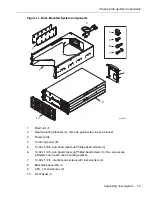
Figure 1-1.
Rack-Mounted System Components
1-3
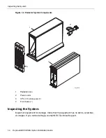
Figure 1-2.
Pedestal System Components
1-4
Figure 2-1.
EIA Square-Hole Pattern on the Vertical Rail
2-3
Figure 2-2.
Numbering the Middle Hole of 4U
2-4
Figure 2-3.
Screw Locations on the Rear Vertical Rails
2-5
Figure 2-4.
Attaching the Mounting Brackets
2-6
Figure 2-5.
Cage Nut Locations on Front Vertical Rails
2-7
Figure 2-6.
Mounting the Shelf Unit on the Mounting Brackets
2-8
Figure 2-7.
Securing the Shelf Unit to the Front Rails
2-9
Figure 2-8.
Securing the Shelf Unit to the Mounting Brackets
2-10
Figure 2-9.
Installing the Backplane Assembly on a Rack-Mounted
System
2-11
Figure 2-10. Installing the Modem Assembly on a Rack-Mounted
System
2-12
Figure 2-11. Installing the CPU-I/O Enclosures into a Cabinet
2-13
Figure 2-12. System in a Cabinet
2-14
Figure 3-1.
Installing the Modem Assembly on a Pedestal System
3-2
Figure 3-2.
Installing the CPU-I/O Enclosures into a Pedestal Case
3-3
Figure 3-3.
CPU-I/O Enclosures Fully Inserted in a Pedestal Case
3-4
Figure 4-1.
Ports on a Pedestal System
4-2
Figure 4-2.
Ports on a Rack-Mountable System
4-3
Figure 4-3.
Connecting a Rack-Mounted System Directly to AC Power
4-8
Figure 4-4.
Connecting a Pedestal System Directly to AC Power
4-9
Figure 4-5.
Connecting a Rack-Mounted System to a UPS
4-11
Figure 4-6.
Connecting a Pedestal System to a UPS
4-12
Figure 4-7.
Connecting the Systems to PDUs
4-14
Figure 5-1.
PDU Components
5-2
Figure 5-2.
Cage Nut Locations: PDU
5-3
Figure 5-3.
Connecting a PDU to a UPS
5-4
Summary of Contents for Express5800/320Ma
Page 1: ...NEC Solutions America Inc NR575 01 Express5800 320Ma System Installation Guide ...
Page 10: ...Preface x Express5800 320Ma System Installation Guide ...
Page 54: ...Removing a PDU from a Cabinet 5 6 Express5800 320Ma System Installation Guide ...
Page 72: ...PDU and PDU Power Cables A 6 Express5800 320Ma System Installation Guide ...