


Connecting the System to Electrical Power
4-8
Express5800/320Ma: System Installation Guide
position. In
Figure 4-3
and in
Figure 4-4
, the interlock
mechanism is shown in the locked position.
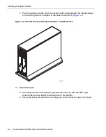
3. Attach a B label to the second power cord. Connect the power cord according to
the system you have:
•
Rack-mounted system: Connect the female end to the receptacle on the
bottom
CPU- I
⁄
O enclosure. Connect the other end to a second, separate,
power source.
•
Pedestal system: Connect the female end to the receptacle on the
left
CPU- I
⁄
O enclosure. Connect the other end to a second, separate, power
source.
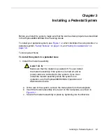
4. From the front of the system, make sure that the CPU- I
⁄
O enclosures are fully
inserted in the shelf unit by tightening, if necessary, the thumbscrews. Then, at the
rear of the system, turn the power interlock mechanisms into the locked position.
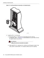
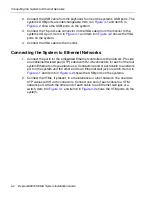
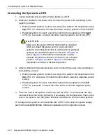
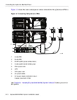
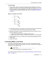
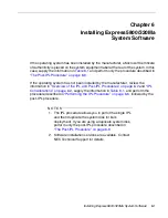
Figure 4-3
shows where the two power cords (not color coded) connect to a
rack-mounted system.
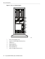
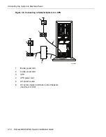
Figure 4-3. Connecting a Rack-Mounted System Directly to AC Power
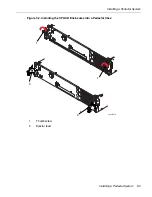
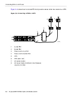
Figure 4-4
shows where the two black power cords connect to a pedestal system.
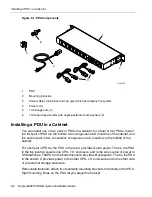
1
B-side power cord
2
A-side power cord
3
AC power outlets
4
AC power (mains) distribution circuit breakers (maximum of 20A)
2
4
3
1
asys001
4
3
Summary of Contents for Express5800/320Ma
Page 1: ...NEC Solutions America Inc NR575 01 Express5800 320Ma System Installation Guide ...
Page 10: ...Preface x Express5800 320Ma System Installation Guide ...
Page 54: ...Removing a PDU from a Cabinet 5 6 Express5800 320Ma System Installation Guide ...
Page 72: ...PDU and PDU Power Cables A 6 Express5800 320Ma System Installation Guide ...


