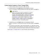
Connecting the System to Ethernet Networks
4-4
Express5800/320Ma: System Installation Guide
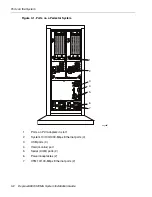
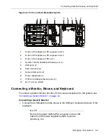
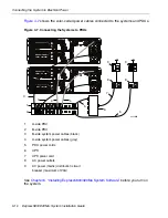
2. Connect the USB cable from the keyboard to one of the system’s USB ports. The
system’s USB ports are interchangeable. Item 3 in
Figure 4-1
and item 5 in
Figure 4-2
shows the USB ports on the system.
3. Connect the 15 pin D-sub connector on the VGA cable from the monitor to the
system’s VGA port. Item 4 in
Figure 4-1
and item 6 in
Figure 4-2
shows the VGA
ports on the system.
4. Connect the VGA cable to the monitor.
Connecting the System to Ethernet Networks
1. Connect the ports for the embedded Ethernet controllers to the network. Provide
an unshielded twisted pair (UTP) cable with RJ-45 connectors for each of the four
system Ethernet ports you plan to use. Connect one end of each cable to a network
port on the system and the other end to an Ethernet wall jack or switch. Item 3 in
Figure 4-1
and item 5 in
Figure 4-2
shows the USB ports on the systems.
2. Connect the VTMs, if present, to a maintenance or other network. You need two
UTP cables with RJ-45 connectors. Connect one end of each cable to a VTM
network port. Attach the other end of each cable to an Ethernet wall jack or a
switch. Item 8 in
Figure 4-1
and item 9 in
Figure 4-2
shows the VTM ports on the
system.
Summary of Contents for Express5800/320Ma
Page 1: ...NEC Solutions America Inc NR575 01 Express5800 320Ma System Installation Guide ...
Page 10: ...Preface x Express5800 320Ma System Installation Guide ...
Page 54: ...Removing a PDU from a Cabinet 5 6 Express5800 320Ma System Installation Guide ...
Page 72: ...PDU and PDU Power Cables A 6 Express5800 320Ma System Installation Guide ...


