background image

78K0/Lx3 - See it!


User’s Manual


U18759EE2V0UM00                                                                       

37


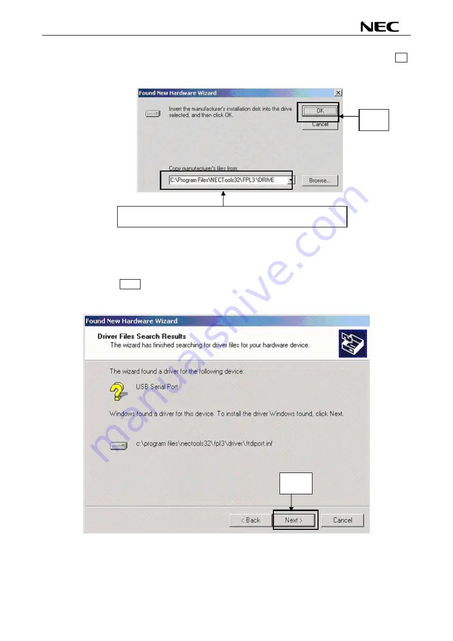
10.  Enter "C:\Program Files\NECTools32\WriteEZ3\DRIVER" in the address bar, then click OK. 


Figure 22: Address Specification 2 (Windows 2000) 


Remark  If the installation destination folder is changed at the time of GUI software installation, 

enter "new-folder\DRIVER". 


11. Click 

Next>. 


Figure 23: Driver File Search 2 (Windows 2000) 


Enter "C:\Program Files\NECTools32\WriteEZ3\DRIVER". 

Click. 

Click. 

Summary of Contents for 78K0/L 3 - See it! Series

Page 1: ...User s Manual 78K0 Lx3 See it Demonstration Kit for the 78K0 L_Series Document No U18759EE2V0UM00 Date Published July 2007 NEC Electronics Europe GmbH ...

Page 2: ... of defects thereof cannot be eliminated entirely To minimize risks of damage to property or injury including death to persons arising from defects in NEC Electronics products customers must incorporate sufficient safety measures in their design such as redundancy fire containment and anti failure features NEC Electronics products are classified into the following three quality grades Standard Spe...

Page 3: ... device The user must take all precautions to avoid build up of static electricity while working with this equipment All test and measurement tool including the workbench must be grounded The user operator must be grounded using the wrist strap The connectors and or device pins should not be touched with bare hands EEDT ST 004 10 Redemption of Waste Electrical and Electronic Equipment WEEE in acco...

Page 4: ...408 588 6000 800 366 9782 Fax 408 588 6130 800 729 9288 NEC Electronics Hong Kong Ltd Hong Kong Tel 2886 9318 Fax 2886 9022 9044 NEC Electronics Europe GmbH Duesseldorf Germany Tel 0211 65 03 0 Fax 0211 65 03 1327 NEC Electronics Hong Kong Ltd Seoul Branch Seoul Korea Tel 02 528 0303 Fax 02 528 4411 Sucursal en España Madrid Spain Tel 091 504 27 87 Fax 091 504 28 60 NEC Electronics Singapore Pte L...

Page 5: ...e it User s Manual U18759EE2V0UM00 5 Revision History Date Revision Chapter Description 21 06 2007 V1 00 First release 20 07 2007 V2 00 5 7 8 9 Changed description from FPL3 to WriteEZ3 FLASH programming software ...

Page 6: ... External A D measurement inputs connector J1 17 3 5 External A D measurement input connector J2 17 3 6 IDD measurement connector J4 17 3 7 External power supply input connector J5 17 3 8 External main oscillator Y1 17 3 9 QB MINI2 connector OCD1 18 3 10 USB interface connector USB1 19 3 11 LCD1 224 segment LCD panel 20 3 12 External LCD resistors RR1 RR5 22 3 13 Temperature sensor U2 22 3 14 IR r...

Page 7: ... 8 4 2 Device menu 49 8 4 3 View menu 58 8 4 4 Help menu 59 8 5 Programmer Parameter Window 60 9 How to use WriteEZ3 FLASH programming software 61 1 Installing the WriteEZ3 GUI software 61 2 Installing the driver 61 3 Installing the parameter file 61 4 Connecting and starting 62 5 Setting the programming environment 63 6 Selecting a user program 66 7 Autoprocedure EPV command execution 67 8 Termin...

Page 8: ...er Installation Completion 2 Windows 2000 38 Figure 25 Found New Hardware Wizard 1 Windows XP 38 Figure 26 Search Location Specification 3 Windows XP 39 Figure 27 Windows XP Logo Testing 3 Windows XP 39 Figure 28 USB Driver Installation Completion 1 Windows XP 40 Figure 29 Found New Hardware Wizard 2 Windows XP 40 Figure 30 Search Location Specification 2 Windows XP 41 Figure 31 Windows XP Logo Te...

Page 9: ...R project download 75 Figure 74 IAR C SPY debugger 76 Figure 75 USB interface cable Mini B type 79 Figure 76 78K0 Lx3 See it schematics 1 2 80 Figure 77 78K0 Lx3 See it schematics 2 2 81 List of Tables Table 1 Operation mode selection SW1 SW2 15 Table 2 Navigation switch SW3 16 Table 3 External A D measurement inputs connector J1 17 Table 4 External A D measurement input connector J2 17 Table 5 Ex...

Page 10: ...parate product from NEC and it is not included in this starterkit package Flexible power supply The 78K0 Lx3 See it supports a flexible configuration of it s power supply The board can be powered by the USB interface the QB MINI2 On Chip debug emulator as well by an external power supply LCD panel 78K0 Lx3 See it provides a 224 segment LCD panel allowing the implementation of human machine interfa...

Page 11: ...Manual U18759EE2V0UM00 11 CAUTION The 78K0 Lx3 See it starterkit is not intended for code development NEC does not allow and does not support in any way any attempt to use 78K0 Lx3 See it in a commercial or technical product ...

Page 12: ...kage contents Please verify that you have received all parts listed in the package contents list attached to the 78K0 Lx3 See it package If any part is missing or seems to be damaged please contact the dealer from whom you received your 78K0 Lx3 See it Note Updates of the IAR Embedded Workbench for 78K FP3 FLASH programming software documentation and or utilities for 78K0 Lx3 See it if available m...

Page 13: ...unctionality by using the IAR C SPY debugger 78K0 Lx3 See it runs the microcontroller at 8 0000 MHz operating speed Per default the internal high speed oscillator of the 78K0 LF3 device is used The Sub clock is provided with 32 768 kHz 2 2 Host computer The USB host interface enables communication to the 78K0 Lx3 See it board The USB UART chip FT232 allows application software to access the USB de...

Page 14: ...d to host computers FLASH programmer or any external target hardware Figure 2 78K0 Lx3 See it board connectors and switches top view Some of the 78K0 Lx3 See it components are free for user application hardware and software Please read the user s manual of the 78K0 LF3 device carefully to get information about the electrical specification of the available I O ports before you connect any external ...

Page 15: ...ction to the Host computer All standard debug function are available in the On Board debug mode like FLASH programming downloading code execution single stepping breakpoints memory manipulation etc 3 1 2 FPL3 WriteEZ3 Mode FLASH programming mode This mode allows to reprogram the internal FLASH memory of the 78K0 LF3 device by using the WriteEZ3 FLASH programming software Within this mode FLASH pro...

Page 16: ...icrocontroller 3 3 Navigation switch SW3 Button SW3 is a navigation switch connected to the key interrupt port of the 78K0 LF3 device It operates in five directions including a center push function The connection of SW3 is shown in the table below Table 2 Navigation switch SW3 SW3 Connection to the 78K0 LF3 device Left P43 KR3 Down P42 KR2 Push P44 KR4 Right P45 KR5 Up P46 KR6 ...

Page 17: ... of the 78K0 LF3 device J2 Signal 1 P23 ANI3 DS1 2 GND Table 4 External A D measurement input connector J2 3 6 IDD measurement connector J4 Connector J4 not assembled can be used to measure the current consumption of the 78K0 LF3 device For using this mode please open soldering bridge V8 3 7 External power supply input connector J5 By using connector J5 not assembled external power supply can be a...

Page 18: ...package OCD1 Signal 1 RESET_IN 2 RESET_OUT 3 FLMDO 4 VDD_IN 5 X2 6 GND 7 X1 8 GND 9 not connected 10 VDD Table 6 QB MINI2 connector OCD1 When using QB MINI2 for debugging purpose please configure switch SW2 of the 78K0 Lx3 See it board as following Mode SW2 SW1 1 2 3 4 5 6 7 8 1 2 3 4 5 6 7 8 ON ON QB MINI2 OFF OFF don t care OFF OFF OFF OFF OFF OFF OFF OFF Table 7 Configuration of SW1 and SW2 whe...

Page 19: ...Additional the WriteEZ3 FLASH programming software uses the USB communication channel to program application software into the CPU internal flash memory The power supply of the 78K0 Lx3 See it board is also provided by the USB1 connector 1 5 Figure 3 Connector USB1 USB Mini B Type Host Connector Pin Configuration Connector USB1 Signal Name 1 VBUS 2 D 3 D 4 not connected 5 GND Table 8 Pin Configura...

Page 20: ... Internal resistance division Bias method 1 4 Timesharing 8 Common signals 8 COM0 COM7 Segment number 28 SEG4 SEG31 Number of maximum display pixels 224 28 segments 8 common Table 9 LCD driver specification The LCD is divided into a character and indicator field The character field is composed of six 5x7 DOT matrix characters The indicator field includes a set of predefined symbols for instance we...

Page 21: ... 320 310 300 000 010 020 030 040 bit5 341 331 321 311 301 001 011 021 031 041 bit4 342 332 322 312 302 002 012 022 032 042 bit3 343 333 323 313 303 003 013 023 033 043 bit2 344 334 324 314 304 004 014 024 034 044 bit1 345 335 325 315 305 005 015 025 035 045 bit0 346 336 326 316 306 006 016 026 036 046 LCD RAM address Bit positio n 9 8 7 6 5 4 3 2 1 0 bit7 Bt3 Battery Bt2 Bt1 BtM An5 Antenna An4 An...

Page 22: ...n of the temperature sensor is connected to pin P21 ANI1 DS0 of the 78K0 LF3 device 3 14 IR receiver module U4 For remote control application an IR receiver module is equipped on the 78K0 Lx3 See it board The output terminal of the IR receiver type RPM7138 is connected to the remote control input pin P41 KR1 RIN of the 78K0 LF3 device 3 15 Buzzer BUZ1 To generate acoustic signals and sound waves a...

Page 23: ... it board provides a wire wrap field area allowing the integration of additional application hardware Figure 5 Connectors T1 T13 and wrap field Connector 78K0 LF3 I O pin T1 P14 SCKA0 INTP4 T2 P32 TOH0 MCG0 T3 P13 SO10 TxD0 T4 P33 TIO00 RTCDIV RTCCL BUZ INTP2 T5 P12 SI10 RxD0 T6 P16 SOA0 TxD6 T7 P30 INTP5 T8 P11 SCK10 T9 P15 SIA0 RxD6 T10 P31 TOH1 INTP3 T11 P10 PCL T12 P120 INTP0 EXLVI T13 P47 KR7...

Page 24: ...losed default connected to VSS A3 Open ANI2 DS1 disconnected from VSS Closed default pin connected to jumper J2 A4 Open ANI3 DS1 disconnected from jumper J2 Closed default connected to VSS A5 Open ANI4 DS2 disconnected from VSS Closed default connected to VDD27 A6 Open ANI5 DS2 disconnected from VDD27 Closed default connected to VSS A7 Open ANI6 REF disconnected from VSS Closed default connected t...

Page 25: ...LF3 memory map The memory layout of 78K0 LF3 device shown in the figure below Figure 6 78K0 LF3 memory map The 78K0 Lx3 See it does not reserve any resources of the 78K0 LF3 device consequently all available memory of the device is free for application software ...

Page 26: ...e FLASH programming downloading code execution single stepping breakpoints memory manipulation etc Additionally 78K0 Lx3 See it supports the QB MINI2 On Chip debug emulator in order to use On Chip debug function of the 78K0 LF3 device The system configuration for On Chip debugging is shown in figure below Figure 7 On Chip Debugging 4 1 OCD via TK 78 debug function To operate the 78K0 Lx3 See it bo...

Page 27: ...hes SW1 and SW2 as following Mode SW2 SW1 1 2 3 4 5 6 7 8 1 2 3 4 5 6 7 8 ON ON QB MINI2 OFF OFF don t care OFF OFF OFF OFF OFF OFF OFF OFF Table 15 Configuration for QB MINI2 debugging Note By supplying power from the QB MINI2 do not connect external hardware to the 78K0 Lx3 See it board Within this mode the 78K0 Lx3 See it board can operate without external power supply from USB ...

Page 28: ...and the 78K0 Lx3 See it board a USB interface line is needed Before you can download debug or execute an application program hardware and software must be installed properly 5 1 1 CD ROM contents The CD ROM shows following directory structure 78K0 Lx3 See it F CD ROM ROOT Acrobat Acrobat Reader for 32Bit Windows OS Doc Documentation WriteEZ3 WriteEZ3 FLASH programming software Drivers USB driver W...

Page 29: ...C For detailed installation hints refer to the following chapters and to the corresponding documentation of the IAR Embedded Workbench 7 1 IAR Systems Embedded Workbench for 78K installation To install the IAR Systems Embedded Workbench for 78K including C SPY debugger simulator select the SETUP program in the directory IAR Embedded Workbench 78K ew78k of the CDROM The setup dialogues will guide y...

Page 30: ...lation on Windows 2000 Page 32 Installation on Windows XP Page 38 7 4 1 Installation on Windows 98SE Me 1 When the 78K0 Lx3 See it board is connected with the host machine the board is recognized by Plug and Play and the wizard for adding new hardware is started Click Next Figure 8 Add New Hardware Wizard Windows 98SE 2 The window below is displayed So check that Search for a suitable driver is se...

Page 31: ... Search Location Specification Windows 98SE 備考 3 1ソフトウエアのインストール先のフォルダを変更した場合は Remark If the installation destination folder is changed at the time of GUI software installation enter new folder DRIVER 4 The window below is displayed Click Next Figure 11 Checking Driver to Be Installed Windows 98SE 1 Check Specify a location only 3 Click 2 Enter C Program Files NECTools32 WriteEZ3 DRIVER Click ...

Page 32: ... USB Serial Port driver is then automatically performed Figure 12 Installation Completion Windows 98SE 7 4 2 Installation on Windows 2000 1 When the 78K0 Lx3 See it board is connected with the host machine the board is recognized by Plug and Play and the wizard for finding new hardware is started Click Next Figure 13 Found New Hardware Wizard 1 Windows 2000 Click Click ...

Page 33: ... suitable driver is selected then click Next Figure 14 Search Method 1 Windows 2000 3 Check the Specify a location check box only then click Next Figure 15 Driver File Location 1 Windows 2000 Click Check that Search for a suitable driver is selected Click Check that Specify a location only is checked ed hed ...

Page 34: ...s bar then click OK Figure 16 Address Specification 1 Windows 2000 Remark If the installation destination folder is changed at the time of GUI software installation enter new folder WriteEZ3 DRIVER 5 Click Next Figure 17 Driver File Search 1 Windows 2000 Enter C Program Files NECTools32 WriteEZ3 DRIVER Click Click ...

Page 35: ...Click Finish to complete the installation of the USB driver Figure 18 USB Driver Installation Completion 1 Windows 2000 7 Proceed to the installation of the USB Serial Port driver Click Next Figure 19 Found New Hardware Wizard 2 Windows 2000 Click Click ...

Page 36: ...or a suitable driver is selected then click Next Figure 20 Search Method 2 Windows 2000 9 Check the Specify a location check box only then click Next Figure 21 Driver File Location 2 Windows 2000 Click Check that Search for a suitable driver is selected Click Check that Specify a location only is checked ...

Page 37: ...dress bar then click OK Figure 22 Address Specification 2 Windows 2000 Remark If the installation destination folder is changed at the time of GUI software installation enter new folder DRIVER 11 Click Next Figure 23 Driver File Search 2 Windows 2000 Enter C Program Files NECTools32 WriteEZ3 DRIVER Click Click ...

Page 38: ... 3 Installation on Windows XP 1 When the 78K0 Lx3 See it board is connected with the host machine the board is recognized by Plug and Play and the wizard for finding new hardware is started Check that Install from a list or specific is selected then click Next Figure 25 Found New Hardware Wizard 1 Windows XP Check that Install from a list or specific is selected Click Click ...

Page 39: ...ress bar then click Next Figure 26 Search Location Specification 3 Windows XP 3 As shown below has not passed Windows Logo testing to verify its compatibility with Windows XP is displayed Click Continue Anyway Figure 27 Windows XP Logo Testing 3 Windows XP 1 Check that Search for the best driver in these locations is selected 2 Check Include this location in the search only Click 4 Click 3 Enter C...

Page 40: ...llation of the USB driver is completed Click Finish Figure 28 USB Driver Installation Completion 1 Windows XP 5 Proceed to the installation of the USB Serial Port driver Click Next Figure 29 Found New Hardware Wizard 2 Windows XP Click Check that Install from a list or specific is selected Click ...

Page 41: ...hen click Next Figure 30 Search Location Specification 2 Windows XP 7 As shown below has not passed Windows Logo testing to verify its compatibility with Windows XP is displayed Click Continue Anyway Figure 31 Windows XP Logo Testing 2 Windows XP 1 Check that Search for the best driver in these locations is selected 2 Check Include this location in the search only 4 Click 3 Enter C Program Files N...

Page 42: ...ee it User s Manual U18759EE2V0UM00 42 8 When the window below is displayed the installation of the USB driver is completed Click Finish Figure 32 USB Serial Port2 Driver Installation Completion Windows XP Click ...

Page 43: ...e Manager tab check that the drivers are installed normally Figure 33 Device Manager For Windows 98SE Me Caution Do not select Update and Erase when communicating with the target device For Windows 2000 XP Caution Do not perform Hardware Modification Scan when communicating with the target device Remark In the GUI port list box the same communication port as COM of USB Serial Port COM needs to be ...

Page 44: ... below for deinstall the USB driver 1 When using Windows XP log on as the computer administrator When using Windows 2000 log on as the Administrator 2 Double click in the order from My Computer to C to Program Files to NECTools32 to WriteEZ3 to DRIVER Ftdiunin exe is displayed Double click Ftdiunin exe Figure 34 Driver Uninstallation 3 Click Continue Figure 35 Driver Uninstaller Double click Click...

Page 45: ... complete driver uninstallation Figure 36 Completion of Driver Uninstallation Caution If the GUI software is uninstalled earlier Ftdiunin exe is also deleted At this time delete USB Serial Port COM and USB High Speed Serial Converter from Device Manager manually Click ...

Page 46: ...e for the PG FP4 from the following NEC Electronics Web site http www eu necel com updates Copy the parameter file downloaded from the NEC Electronics Web site into sub directory WriteEZ3 EXE install path PRM created during GUI software setup refer to CHAPTER 7 SOFTWARE INSTALLATION 8 2 Starting up the GUI Software GUI software startup Select WriteEZ3 EXE from the start menu to start the WriteEZ3 ...

Page 47: ...window displayed under the toolbar Displays an WriteEZ3 action log Programmer parameter window displayed to the right of the action log window Displays programming parameter settings Status bar Displays status 8 3 Toolbar The toolbar contains buttons for starting the important procedures of the WriteEZ3 Figure 38 Toolbar Buttons Device Setup button File Load button Device Blank Check button Device...

Page 48: ...ogram file The selected program file is programmed into the flash memory of the device by executing the Program command or Autoprocedure EPV command Figure 40 HEX File Selection Window The file selection window for program loading displays the most recently used directory to which a user program has been loaded After a user program is loaded a checksum calculation is made and the result is display...

Page 49: ...ice Figure 41 Device Menu 1 Blank Check command The Blank Check command allows you to make a blank check on the target device connected to the WriteEZ3 If the flash memory of the target device is erased a blank check is terminated normally If the flash memory is not completely erased the indication not blank is provided Before starting programming erase the flash memory of the target device 2 Eras...

Page 50: ...tion the GUI software displays the result of executing the command on the target device 5 Security command The Security command initiates the programming of the security flag of the target device connected to the WriteEZ3 Set Security flag settings on the Advance tab of the Device Setup menu 6 Checksum command The Checksum command reads the checksum value of the target device connected with the Wr...

Page 51: ...p This menu is used to set the environment for rewriting the flash memory of the target device The mode of communication with the target the operating clock and so forth differ depending on the device used For details refer to the manual of the device used when making settings The window shown below is opened Figure 42 Device Setup Window Standard This window shows all basic options that can be se...

Page 52: ...cause the data is related to the guarantee of rewrite data The parameter file is protected by the checksum function If the checksum result indicates an error the WriteEZ3 does not accept the parameter file Figure 43 Device Setup Window Parameter File Selection Figure 44 Parameter File Selection Window PRM File Read button A window for specifying a parameter file is displayed Specify a desired file...

Page 53: ...d 3 Supply oscillator Supply oscillator is used to select a clock that determines programming data transfer and a transfer rate Figure 46 Device Setup Window Supply Oscillator Selection Frequency box Sets the clock frequency of the target system The range of operating frequency varies from one device to another So check the specifications of the device used before making a setting Multiply rate Sp...

Page 54: ... processing by using Start End The Start End list boxes display the Block numbers where the flash memory of the target device is configured When Area is selected Specify the Area number range subject to rewrite processing by using Start End The Start End list boxes display the Area numbers where the flash memory of the target device is configured Show Address check box Specify whether numbers or a...

Page 55: ...Erase check box If this check box is checked blank check is made before the Erase command or EPV command is executed If the result of a blank check indicates OK erase processing is not executed Read verify after Program check box If this check box is checked write data is sent from the programmer after execution of the Program command and EPV command then the data is verified against the data writ...

Page 56: ...51 Device Setup Window Security flag settings Caution The following is the correspondence between the Erase and Program Commands when the security functions of a 78K0 LF3 microcontroller are valid Chip Erase Command Block Erase Command Program Command Disable Chip Erase Invalid Invalid Valid Note1 Disable Block Erase Valid Invalid Valid Disable Program Valid Invalid Invalid Disable Boot block clus...

Page 57: ...Erase command when Chip was selected under Operation Mode Disable Program check box If this check box is checked the Program command becomes invalid as does the Erase command in all the blocks of the flash memory selected under Operation Mode in the Standard Setup menu The Erase command for the entire flash memory area is valid This setting is cleared by the Erase command when Chip was selected un...

Page 58: ...s menu contains commands for setting whether to display the toolbar and status bar Figure 54 View Menu 1 Toolbar command Checking the Toolbar command displays the toolbar Unchecking the command hides the toolbar 2 Status Bar command Checking the Status Bar command displays the status bar Unchecking the command hides the status bar ...

Page 59: ...icking the Help menu displays the following pull down menu Figure 55 Help Menu 1 About WriteEZ3 command The About WriteEZ3 command opens the program entry window as shown below and indicates the version Clicking OK terminates the display Figure 56 About WriteEZ3 Window ...

Page 60: ...munication with the target device to display information about the target device Parameter file Updated after Setup command execution to display information about a read parameter file Load file Updated after Load command execution to select information about a selected program file Connection to device Updated after Setup command execution to display information about the connection with the targ...

Page 61: ...eck before Erase 1 Installing the WriteEZ3 GUI software Install the WriteEZ3 GUI software on the host machine you are using by referring to CHAPTER 7 SOFTWARE INSTALLATION if the software has not been installed yet 2 Installing the driver Install the USB driver on the host machine you are using by referring to CHAPTER 7 SOFTWARE INSTALLATION if the driver has not been installed yet 3 Installing th...

Page 62: ...tching SW1 and SW2 to the following setting Mode SW2 SW1 1 2 3 4 5 6 7 8 1 2 3 4 5 6 7 8 ON ON ON ON ON ON FPL3 WriteEZ3 OFF OFF don t care OFF OFF OFF OFF 2 Plug and Play Connect the 78K0 Lx3 See it board with the host machine via the USB cable If the connection was already done press the reset button SW4 to release the FLASH programming mode SW1 SW2 ...

Page 63: ...00 63 3 Start the WriteEZ3 GUI Figure 58 GUI Software Startup Screen 5 Setting the programming environment 1 Select Device Setup from the menu bar 2 The Standard dialog box for device setup is activated Figure 59 Standard Device Setup Dialog Box ...

Page 64: ...m then click Open Figure 60 Parameter File Selection 4 From the Port list box select the communication port that matches the host machine being used Select the communication speed of the Host connection Figure 61 Port Selection Remark Selectable ports can be checked using Device Manager For details refer to 7 6 Confirmation of USB Driver Installation ...

Page 65: ...board Frequency 6 00 MHz and Multiply rate 1 00 In Operation Mode please specify the Chip mode The following figure shows the recommended settings Figure 62 Standard Device Setup Dialog Box after Setting 6 Switch to the Advance dialog box Figure 63 Advance Device Setup Dialog Box Command options Blank check before Erase Checked ...

Page 66: ...leted the following screen is displayed Figure 64 Completion of Parameter Setting 6 Selecting a user program 1 Select File Load 2 Select a program file to be written to the target device then click Open Figure 65 After Downloading The display is updated Success read HEX file is displayed PRM File Read OK is displayed The display is updated ...

Page 67: ...uit to terminate the GUI software All settings executed so far are saved in the WriteEZ3 INI file so that those settings can be reused when the GUI software is restarted 9 Execute the VOLTMETER application Set the 78K0 Lx3 See it board to the normal operation mode QB MINI2 mode Plug and Play the 78K0 Lx3 See it board to start in normal operation mode or press the reset button SW4 to release the no...

Page 68: ...rt of the personal computer Alternatively disconnect the USB connector from the USB port then insert the USB connector again after a while Cause The driver may not be installed correctly Action 1 When this product is connected to the personal computer right click the driver marked with or Click Erase when displayed 2 On Device Manager execute Hardware Modification Scan 3 Install the driver again w...

Page 69: ...WriteEZ3 may not be set correctly Action Set the port checked using Device Manager Cause The 78K0 Lx3 See it board is operating in normal mode Action Set the board to the WriteEZ3 FLASH programming mode Cause The PRM file selected in Device Setup may be incorrect Action Use the corresponding PRM file that matches the target device For information about the PRM file refer to CHAPTER 8 WRITEEZ3 FLAS...

Page 70: ...e USB driver first The communication between the starterkit and the IAR C SPY debugger that is running on the personal computer is done via the standard UART USB connection To operate the 78K0 Lx3 See it board within the TK 78 On Board debug mode configure switches SW1 and SW2 as following Mode SW2 SW1 1 2 3 4 5 6 7 8 1 2 3 4 5 6 7 8 ON ON ON ON ON ON ON ON On Board Debug OFF OFF don t care OFF OF...

Page 71: ...tart menu Programs folder IAR Systems IAR Embedded Workbench Kickstart for 78K The following screen appears Figure 67 IAR Embedded Workbench Now select the option Open exiting workspace from the File menu and locate the sample project Open the file 78K0LX3_SEEIT_SAMPLES eww This is the workspace file that contains general information about the demonstration projects and settings ...

Page 72: ...ect workspace As a next step check some settings of the IAR Embedded Workbench that have to be made for correct operation and usage of the On Board debug function of the 78K0 Lx3 See it board First highlight the upper folder called Voltmeter Debug in the workspace window Then select Project Options from the pull down menus Next select the category Debugger Make sure that the driver is set to TK 78...

Page 73: ... the corresponding serial port Figure 70 IAR debugger options 2 2 Next the correct linker settings of the demo project will be checked This can be done in the Linker category as shown below Select the Config tab and check that the linker command file lnk78f0495 xcl is selected This file is used by the linker and contains information on where to place the different sections of code and data that ma...

Page 74: ...t errors it can now be downloaded to the 78K0 Lx3 See it board and debugged To start the IAR C SPY debugger select the option Debug from the Project menu or press the Debugger button In the next step the TK 78 Emulator has to be configured before downloading a new application Press the OK button to enter the hardware setup menu Set the configuration as show in the figure below and start the downlo...

Page 75: ...bugger is started and the demo project is downloaded to the 78K0 Lx3 See it board The progress of downloading is indicated by blue dots in the TK 78 Emulator window Please note downloading of larger executables can take some time Figure 73 IAR project download ...

Page 76: ...s of IAR C SPY debugger are available i e Single Stepping Step Over In Out Go Stop Breakpoints Register Memory view etc To get more details on the debugger configuration and capabilities please refer to the 78K IAR Embedded Workbench IDE User Guide of the IAR installation Figure 74 IAR C SPY debugger ...

Page 77: ...oject and output files RemoteControl 78K0 LF3 project and output files Temperature 78K0 LF3 project and output files Voltmeter 78K0 LF3 project and output files 78K0LX3_SEEIT_SAMPLES eww workspace file IAR Embedded Workbench for 78K Table 17 Example directory structure The main directory contains only the project files for the IAR Systems Embedded Workbench for 78K All source files are located in ...

Page 78: ...ntrol input pin P41 KR1 RIN of the 78K0 LF3 device By running the sample custom code and data code in the NEC format that is transmitted by an external remote controller can be received The received data is displayed alternately 16 bit wise on the LCD panel 12 5 Temperature sample The temperature measurement is realized by using the onboard temperature sensor IC type S 8120C and both A D converter...

Page 79: ...78K0 Lx3 See it User s Manual U18759EE2V0UM00 79 13 Cables 13 1 USB interface cable Mini B type Figure 75 USB interface cable Mini B type ...

Page 80: ...78K0 Lx3 See it User s Manual U18759EE2V0UM00 80 14 Schematics Figure 76 78K0 Lx3 See it schematics 1 2 ...

Page 81: ...78K0 Lx3 See it User s Manual U18759EE2V0UM00 81 Figure 77 78K0 Lx3 See it schematics 2 2 ...

Page 82: ...78K0 Lx3 See it User s Manual U18759EE2V0UM00 82 memo ...

Reviews: