background image

En-30

 Special characters in the PROGRAM TIMER

screen

When the setting item includes gray indication, it does
not function under the timer’s setting.

P RO G R A M   T I M E R

DAY

MON

TUE
SAT

*

FRI

SAT

*

INPUT

RGB2

VIDEO1

DVD1


RGB1

FUNC.

INV.

WHITE


REP.1


ON

08 : 30

- - : - -


08 : 30
08 : 30

- - : - -


08 : 30
15 : 30

- - : - -

OFF

10 : 30

18 : 15
12 : 15
10 : 00

- - : - -


12 : 15
16 : 00

- - : - -

1
2
3
4
5
6
7
8

• An asterisk “

*

” in the DAY field

An asterisk “*” means “every” or “everyday”. For
example, “*FRI” means “every Friday”. If you enter
“*” only, it means “everyday”.

• A hyphen “

-

” in the ON field or OFF field

You have to set at least the ON field or OFF field to
activate the program timer.

• A hyphen “

-

” in the INPUT and FUNC. field

A hyphen “-” in the INPUT field means the last mode.
When you set “REP.1~3” in the FUNC. field, the
INPUT field is set to “-”.

 To set MULTI INPUT

• Set the INPUT field to “MULTI”, then press the

MENU/ENTER button.
The “MULTI SCREEN SETTING” will appear on
the screen.

• Use the 

 and 

 buttons to select “MULTI MODE”,

then use the 

 and 

 buttons to choose from

“SINGLE”, “SIDE BY SIDE1~3” and “PICTURE
IN PICTURE (BOTTOM LEFT~TOP LEFT)”.

• Use the 

 and 

 buttons to select “MAIN”/ “SUB”

and “LEFT”/“RIGHT”, then use the 

 and 

 buttons

to choose from “VIDEO1~3”, “DVD1~2” and
“RGB1~3”.

PICTURE IN PICTURE          SIDE BY SIDE

 To set “REP.1~3” to the FUNC.

• Set the function to “REP.1”, “REP.2” or “REP.3”, then

press the MENU/ENTER button.
The “REPEAT TIMER” screen will appear on the
screen.

• Use the 

 and 

 buttons to choose from “SINGLE”,

“MULTI” and “VIDEO-W”, then adjust the items.

• When you set FUNC. to “REP.1”, “REP.2” or

“REP.3”, you can set “SINGLE”, “MULTI” and
“VIDEO-W”. However, only one of these works
depending on the settings of AUTO ID and DIVIDER.
See “REPEAT TIMER” on page En-30 for details
for the above settings.

PROGRAM TIMER

This sets the day and time at which the power will be
switched ON/OFF as well as the input mode.

Example 1: Setting so that the power will be switched
on at 8:30 A.M., Monday, displaying RGB2 source,
and switched off at 10:30 A.M.

On “TIMER” menu, select “PROGRAM”, then press the
MENU/ENTER button.
The “PROGRAM TIMER” screen appears.
Adjust the items.
Use the 

▲▼

 and 


 buttons to move the cursor.

Each mode switches each time the ZOOM 

/

 button is

pressed.
Depending on the selected INPUT or FUNC., press the
MENU/ENTER button to make advanced settings.

SEL.

OK

P RO G R A M   T I M E R

EXIT

ZOOM

ADJ.

DAY

MON


INPUT

RGB2


ON

08 : 30

- - : - -


- - : - -


- - : - -


- - : - -


- - : - -


- - : - -
- - : - -
- - : - -

- - : - -


OFF

10 : 30

- - : - -


- - : - -


- - : - -


- - : - -


- - : - -


- - : - -
- - : - -
- - : - -
- - : - -

1
2
3
4
5
6
7
8
9

10

FUNC.

INV.


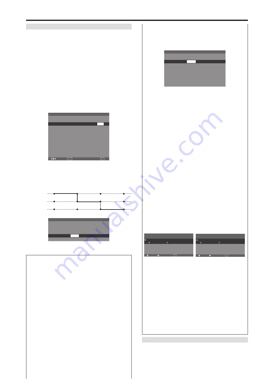
Example 2: Setting so that the power will be switched
on at 8:00 A.M., Monday, displaying the VIDEO1
input, display the RGB1 input at 9:00 A.M., display in
WHITE at 10:00 A.M., then switched off at 11:00 A.M.

P RO G R A M   T I M E R

DAY

MON
MON
MON

INPUT

VIDEO1

RGB1


ON

08 : 00
09 : 00
10 : 00

- - : - -


1
2
3
4

FUNC.


WHITE

OFF

- - : - -

- - : - -


11 : 00


- - : - -


* To perform a continuous program, set the OFF time only

for the last item.

Information

 PROGRAM TIMER settings

DAY:

 Set the day of the week (e.g. Sunday).

ON (hour, minutes):

 Set the time at which the power

will be turned on in the 24-hour format.

OFF (hour, minutes):

 Set the time at which the power

will be turned off in the 24-hour format.

INPUT:

 Set the input mode that will be displayed when

the power is turned on from “VIDEO1~3”, “DVD1~2”,
“RGB1~3” and “MULTI”.

FUNC.:

 Set the function that will be activated after the

power is turned on from “ORB.”, “INV.”, “WHITE”,
“WIPER” and “REP.1~3”.
“REP.1~3” cannot be selected when INPUT is set.

 To reset the program

Align the cursor with the DAY field that you wish to
reset, then press the CLEAR/SEAMLESS SW button.

 To reset the data

Align the cursor with the field (ON/OFF/INPUT/
FUNC.) that you wish to reset, then press the CLEAR/
SEAMLESS SW button.

8:00

9:00

10:00

11:00

ON

OFF

PROGRAM 1

PROGRAM 2

PROGRAM 3

VIDEO1

RGB1

WHITE

REPEAT TIMER

This function enables you to display 2 input modes at the
set time alternately.

Example: Setting to display “VIDEO1” for 10 minutes
and “DVD1” for 15 minutes alternately.

On “TIMER” menu, select “REPEAT”, then press the
MENU/ENTER button.

SEL.

ADJ.

RETURN

P RO G R A M   T I M E R

M U LT I   S C R E E N   S E T T I N G

M U LT I   M O D E
  :        S I D E   B Y   S I D E 1
I N P U T   M O D E  
  L E F T  
  R I G H T

:      R G B 1
:     V I D E O 1

EXIT

SEL.

ADJ.

RETURN

P RO G R A M   T I M E R

M U LT I   S C R E E N   S E T T I N G

M U LT I   M O D E
  :        B OT TO M   L E F T
I N P U T   M O D E  
  M A I N  
  S U B

:      R G B 1
:     V I D E O 1

EXIT

Summary of Contents for 60XM5 - PlasmaSync - 60" Plasma Panel

Page 1: ...anced split screen Model PlasmaSync 42XM5 PX 42XM5G PlasmaSync 50XM6 PX 50XM6G PlasmaSync 60XM5 PX 60XM5G User s Manual Benutzerhandbuch Manuel d utilisation Manual del Usuario Manuale dell utente Bru...

Page 2: ...User s Manual Enhanced split screen Model ENGLISH...

Page 3: ...re hazard 2 Handle the unit carefully when installing it and do not drop 3 Set the unit away from heat excessive dust and direct sunlight 4 Protect the inside of the unit from liquids and small metal...

Page 4: ...r cable supplied and then use the bands supplied tofastentheferritecores supplied tothepower cable supplied If you do not this this monitor will not conform to mandatory CE or C Tick standards Power c...

Page 5: ...colors En 22 Audio Settings Menu En 23 Adjusting the treble bass and left right balance and audio input select En 23 Setting the allocation of the audio connectors En 23 Image Adjust Settings Menu En...

Page 6: ...zed dealer Failure to follow correct mounting procedures could result in damage to the equipment or injury to the installer Product warranty does not cover damage caused by improper installation Drawi...

Page 7: ...l Connect signal cables and remote cables as shown below Video signal RGB DVD HD signal VIDEO IN OUT IN OUT AUDIO 1 DVD1 HD1 R 1 3 2 MONO L Y Cb Pb Cr Pr RGB2 DVD2 HD2 RGB 1 VD HD DVI Digital RGB R L...

Page 8: ...remote control mode Connect the remote cable to the remote control s remote jack and the REMOTE IN terminal on the monitor When the cable is connected the mode automatically switches to wired remote c...

Page 9: ...used to adjust the picture parameters in the On Screen Menu OSM mode y VOLUME DOWN and UP Adjusts the volume Functions as the CURSOR buttons in the On Screen Menu OSM mode u MENU ENTER Sets the On Scr...

Page 10: ...signal TMDS from a source with a DVI output This input can be set for use with an RGB3 I EXTERNAL CONTROL This terminal is used when operating and controlling the monitor externally with a control sy...

Page 11: ...signal TMDS from a source with a DVI output This input can be set for use with an RGB3 I EXTERNAL CONTROL This terminal is used when operating and controlling the monitor externally with a control sy...

Page 12: ...e F RGB2 DVD2 HD2 RGB2 You can connect an analog RGB signal and the syncronization signal DVD2 HD2 You can connect DVDs High Definition sources Laser Discs etc here This input can be set for use with...

Page 13: ...SPLAY Displays the source settings on the screen 4 OFF TIMER Activates the off timer for the unit 5 SIDE BY SIDE Press this button to show a couple of pictures in the side by side mode 6 PICTURE IN PI...

Page 14: ...e pointer will change to resemble a magnifying glass A press of the ZOOM button will reduce the picture and return it to its original size To change the picture position Select the position with the b...

Page 15: ...heater size wide movies etc 2 35 1 size screen The squeezed film image is expanded to fulfill the entire screen at a ratio of 2 35 1 Black bands do not appear at the top and bottom but information is...

Page 16: ...BM Inc of the United States Note Do not allow 4 3 content to be displayed for extended periods of time without using gray bars This can cause image retention Wide Screen Operation with Computer Signal...

Page 17: ...button VIDEO1 RGB1 A B VIDEO1 RGB1 B A To make the desired picture active press the SELECT FREEZE button VIDEO1 RGB1 A B VIDEO1 RGB1 A B VIDEO1 RGB2 A B VIDEO1 RGB2 A B VIDEO1 RGB2 B A VIDEO1 RGB2 A...

Page 18: ...so be used to change the selection Zooming in on a specific input 1 Press the SELECT FREEZE button to make the desired picture active 2 Use the POINTER button and the ZOOM button to enlage the picture...

Page 19: ...sub menu or item SEL ADJ RETURN PICTURE 1 2 CONTRAST BRIGHTNESS SHARPNESS COLOR TINT PICTURE MODE NR NEXT PAGE NORMAL OFF 52 32 16 32 32 G R EXIT 4 Adjust the level or change the setting of the selec...

Page 20: ...BALANCE L R 22 0 22 YES YES En 23 AUDIO INPUT1 VIDEO 1 3 DVD HD 1 2 RGB 1 3 YES YES En 23 AUDIO INPUT2 VIDEO 1 3 DVD HD 1 2 RGB 1 3 YES YES En 23 AUDIO INPUT3 VIDEO 1 3 DVD HD 1 2 RGB 1 3 YES YES En...

Page 21: ...1 No 4 No 7 No 15 No 16 No 31 No 32 No 56 NO En 33 DISP MODE SPLIT BLANK YES NO En 33 AUTO ID OFF ON YES NO En 33 IMAGE ADJUST ASPECT MODE NORMAL FULL STADIUM ZOOM 2 35 1 14 9 UNDERSCAN TRUE 3 NO En 3...

Page 22: ...32 G R EXIT PICTURE MODE THEAT 1 Reducing noise in the picture Use these settings if the picture has noise due to poor reception or when playing video tapes on which the picture quality is poor Examp...

Page 23: ...TONE COLOR TUNE MID 3 MODE1 Information GAMMA settings The picture becomes darker as the number increases in the sequence of 1 2 3 4 Making the Low Tone adjustments You can select the tone reproductio...

Page 24: ...utton on the remote control The settings on the IMAGEADJUST menu are not preset at the factory SEL ADJ RETURN IMAGE ADJUST ASPECT MODE V POSITION H POSITION V HEIGHT H WIDTH AUTO PICTURE FINE PICTURE...

Page 25: ...N The position of the menu will be shifted by eight dots each time OSM is displayed OFF OSM will be displayed at the same position OSM CONTRAST settings NORMAL OSM brightness is set to normal LOW OSM...

Page 26: ...y all signals ON If no input signal is present skip that signal SETTING NOW will appear during the input search Resetting to the default values Use these operations to restore all the settings PICTURE...

Page 27: ...mode suited to the picture NTSC PAL PAL60 480I 60 Hz 525I 60 Hz 576I 50 Hz 625I 50 Hz 1035I 60 Hz 1080I 60 Hz only Example Setting the CINEMA MODE to OFF On CINEMAMODE of OPTION2 menu select OFF SEL A...

Page 28: ...rval of 1 minute to 5 minutes 1 horizontal dot or 1 vertical line per interval INVERSE Use this to set the inverse mode or to display a white screen Example Setting INVERSE to WHITE On INVERSE of LONG...

Page 29: ...ges and softens the image Example Setting SOFT FOCUS to 2 On SOFT FOCUS of LONG LIFE menu select 2 SEL ADJ RETURN EXIT LONG LIFE PLE ORBITER INVERSE SCREEN WIPER SOFT FOCUS AUTO AUTO1 OFF OFF 2 Inform...

Page 30: ...the day of the week time and the input mode you want or repeat timer which displays two input modes alternately On OPTION3 menu select TIMER then press the MENU ENTER button The TIMER screen appears S...

Page 31: ...select PROGRAM then press the MENU ENTER button The PROGRAM TIMER screen appears Adjust the items Use the and buttons to move the cursor Each mode switches each time the ZOOM button is pressed Dependi...

Page 32: ...ously REPEAT TIMER SEL ADJ RETURN 1 DIVIDER WORK TIME INPUT MODE 2 DIVIDER WORK TIME INPUT MODE 1 00H03M VIDEO1 2 2 00H06M RGB1 EXIT REPEAT TIMER VIDEO WALL Setting the power on mode This function set...

Page 33: ...emote control Example Setting to 1 On the REMOTE ID of OPTION3 menu select 1 SEL ADJ RETURN OPTION 3 3 4 PREVIOUS PAGE TIMER PWR ON MODE CONTROL LOCK IR REMOTE LOOP OUT REMOTE ID ID NUMBER VIDEO WALL...

Page 34: ...SITION POSITION NO 4 EXIT NO 1 NO 2 NO 4 NO 3 NO 7 NO 8 NO 9 NO 10 NO 11 NO 12 NO 13 NO 14 NO 15 NO 16 NO 17 NO 18 NO 19 NO 20 NO 21 NO 22 NO 23 NO 24 NO 25 NO 26 NO 27 NO 28 NO 29 NO 30 NO 31 NO 32 N...

Page 35: ...one by one automatically From the second monitor onward neither the POWER button on the unit nor the POWER ON button on the remotecontrolworks However bypressingandholding the POWER ON button for mor...

Page 36: ...ample Setting ZOOM NAV to S BY S On ZOOM NAV of OPTION4 menu select S BY S SEL ADJ RETURN OPTION 4 4 4 PREVIOUS PAGE SUB PICTURE ZOOM NAV PIC FREEZE SEAMLESS SW SELECT1 SELECT2 TEXT INSERT S BY S S BY...

Page 37: ...gnal analysis SEAMLESS SW settings OFF Turns off the SEAMLESS SW function ON When the CLEAR SEAMLESS SW button is pressed input signals will switch quickly according to the setting of SELECT1 and SELE...

Page 38: ...URCE INFORMATION then press the MENU ENTER button The SOURCE INFORMATION is displayed RETURN SOURCE INFORMATION H FREQUENCY V FREQUENCY H POLARITY V POLARITY MEMORY RESOLUTION 48 4KHZ 60 0HZ NEG NEG 2...

Page 39: ...1H 09H 1AH 2 35 1 DFH 80H 60H 51H 01H 0AH 1BH Auto Picture ON DFH 80H 60H 7FH 03H 03H 09H 00H 4DH OFF DFH 80H 60H 7FH 03H 03H 09H 01H 4EH Cinema Mode ON DFH 80H 60H C1H 01H 01H 82H OFF DFH 80H 60H C1H...

Page 40: ...l connection and operation Connection Example STB has the REMOTE IN connector The pin assignment of the REMOTE IN connector of STB is same as that of 1 8 stereo mini cable connected to the REMOTE OUT...

Page 41: ...input signal Promptly switch off the power of the main unit and wait until the internal temperature drops See 1 Prompty switch off the power of the main unit See 2 Symptom The unit emits a crackling...

Page 42: ...4 1152 864 1280 768 1280 768 1280 768 1280 800 1280 854 1360 765 1360 768 1376 768 1280 1024 1400 1050 1680 1050 1600 1200 1920 1080 1920 1080 1920 1200 1920 1200RB Horizontal NEG NEG NEG NEG NEG NEG...

Page 43: ...nym for High bandwidth Digital Content Protection High bandwidth Digital Content Protection HDCP is a system for preventing illegal copying of video data sent over a Digital Visual Interface DVI If yo...

Page 44: ...152 864 1280 768 1280 768 1280 768 1280 800 1280 854 1360 765 1360 768 1376 768 1280 1024 1400 1050 1680 1050 1600 1200 1920 1080 1920 1080 1920 1200 1920 1200RB Horizontal NEG NEG NEG NEG NEG NEG NEG...

Page 45: ...DCP HDCP technology HDCP is an acronym for High bandwidth Digital Content Protection High bandwidth Digital Content Protection HDCP is a system for preventing illegal copying of video data sent over a...

Page 46: ...576I 625I NTSC 480I 525I Digital Zooming 100 to 900 Selectable Video Wall 4 25 multi screens Self Diagnosis via RS232C Long Life Mode PEAK BRIGHT ORBITER INVERSE WHITE SCREEN WIPER SOFT FOCUS etc Cont...

Page 47: ...PAL 576I 625I NTSC 480I 525I Digital Zooming 100 to 900 Selectable Video Wall 4 25 multi screens Self Diagnosis via RS232C Long Life Mode PEAK BRIGHT ORBITER INVERSE WHITE SCREEN WIPER SOFT FOCUS etc...

Page 48: ...PAL 576I 625I NTSC 480I 525I Digital Zooming 100 to 900 Selectable Video Wall 4 25 multi screens Self Diagnosis via RS232C Long Life Mode PEAK BRIGHT ORBITER INVERSE WHITE SCREEN WIPER SOFT FOCUS etc...

Reviews: