background image

 Page 12

6

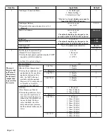
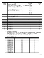
Echo Canceller Mode

1: Enable

2: Disable

1

Echo Canceller Tail size (Delay Volume)

1: 8ms

2: 16ms

2

Echo Canceller Nonlinear Processor

1: Enable

2: Disable

1

Echo Canceller NLP Comfort Noise Level

0-30

Entries:

0 = -70
1 = -69
2 = -68
3 = -67

|

28 = -42
29 = -41
30 = -40

0

Echo Canceller NLP Comfort Noise 
Configuration

0: Adaptive

1: fixed

0

Echo Canceller 4 Wire-Detect

0: Disable

1: Enable

1

7

Silence Suppression VAD Configuration

¥ Detects the period of silence and send the Nil 

Packet to reduce the network traffic.

0: Disable

1: Enable

0

Silence Suppression VAD Power Threshold

¥ Define the threshold of the nil voice level to 

detect the period of silence.

0 or 20-50

VAD Power Threshold Entries:

0 = Adaptive threshold

20 = -20
21 = -21
22 = -22

|

48 = -48
49 = -49
50 = -50

0

8

DTMF Relay Mode

0: Disable (In-Band Signaling)

1: Enable (Out-of-Band Signaling)

1

DTMF Relay Type

¥ Define the type of DTMF Relay. With  In-Band , 

the DTMF signal is on the extension header of 
the RTP (UDP), and it is sent to the destination. 
With  Out-Band , the DTMF signal is sent to the 
destination with H.245 User Input (TCP).

1: In-bandwidth (Rfc2833)

2: Out-bandwidth (H.245)

2

DTMF Low Band Amplitude

¥ Define the low band level of DTMF signals from 

the VOIPU to the PCM highway when the 
VOIPU receives the packet including DTMF 
information.

Note: If the VoIPU PCB is working, changing 
this option will cause the PCB to reset.

0-830

Low Band Amplitude Entries:

0 = -80.0
1 = -79.9
2 = -79.8
3 = -79.7

|

800 = 0

|

828 = 2.8
829 = 2.9
830 = 3.0

670

Item No.

Item

Input Data

Default

Summary of Contents for 124i Enhanced

Page 1: ...124i Enhanced 4 VoIP PCB Installation Manual 20100 ...

Page 2: ...nge without notice and NEC America has no obligation to provide any updates or corrections to this manual Further NEC America also reserves the right without prior notice to make changes in equipment design or components as it deems appropriate No representation is made that this manual is complete or accurate in all respects and NEC America shall not be liable for any errors or omissions In no ev...

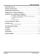
Page 3: ...Calls If Not Using a Gatekeeper 2 Configuration for IP Address Determination 3 How to Determine the Destination IP Address with ARS Required if Dialing More Than 4 Digits 3 Dial Edit 5 Calling Party Number 5 F Route Setting for IP Address 5 Incoming Calls 6 DID Error Routing Settings 6 VoIP PCB Setup Examples 7 Conditions 8 Installation 8 Programming 9 Firmware Upgrade 16 ...

Page 4: ...Table of Contents Table of Contents 2 92046INS01 ...

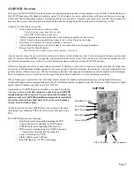
Page 5: ...al H 323 Gatekeeper Each client is required to register with an H 323 Gatekeeper and provide an IP address and telephone number to be used as an alias From this information the Gatekeeper constructs routing tables and provides clients with directory services When a Gatekeeper is installed all routing and call initialization must be handled by the Gatekeeper The 124i Enhanced system will not be all...

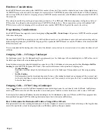
Page 6: ...er If a Gatekeeper is used the 124i Enhanced must be programmed to use the Gatekeeper All user dialed digits for a VoIP call are sent to the Gatekeeper which will set up and manage the call Some Gatekeepers accept overlap dial information some do not The 124i Enhanced system can enable either Overlap or En Bloc Sending for each VoIP PCB Program 0319 Item 1 This results in differences in the operat...

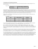
Page 7: ...tination IP Address with ARS Required if Dialing More Than 4 Digits If you want to dial the phone number to reach an IP telephone when a Gatekeeper is not available the ARS feature should be used ARS uses the 3 digit or 6 digit table to decide the trunk group to be used An option is now available to convert the dialed digits to an IP address If the ARS selection number is found by searching the 3 ...

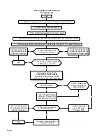
Page 8: ...found Does the table have a trunk group setting in Program 0604 No Yes No Yes Stop The trunk group and IP address in Program 0928 are used to route the call Stop Start The trunk group number from the Selection Route Table Program 2101 is used for the call Is this a VoIP trunk group number 101 to 126 Use the last 2 digits of the trunk group number as the entry point to Program 0928 Yes The call is ...

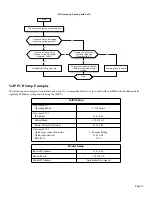
Page 9: ...178 10 2 Program the VoIP PCB Operating Mode In 0319 assign the slot number in which the VoIP PCB is installed Program the Hardware Settings for the VoIP In 0153 set the following Item 1 IP Address System A 192 178 10 1 System B 192 178 10 2 Subnet Mask 255 255 0 0 Default Gateway Address 192 178 10 10 Item 5 Fast Connect Mode Fast Connect Mode 2 Program the VoIP Trunk Group In Program 0905 assign...

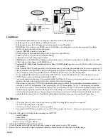
Page 10: ...ll can be connected to any of the ports on the PCB so the trunk service type has to be the same for all the trunks on the same PCB Basic system settings are essentially the same as ISDN trunks The routing programing is also the same However as incoming calls may have a called party number it is recommended that DID service type be used Program 0901 Items 14 17 and 32 35 set to 3 Incoming calls may...

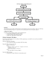
Page 11: ... 2 Gatekeeper connection mode Gatekeeper Address RAS Port 1 Manual Setting 128 10 0 3 1719 Router Setup Router IP Address 128 10 0 2 Subnet Mask 255 255 0 0 Global IP Address Automatically assigned DID Incoming Routing with VoIP The system detects an incoming call Is there a Called Party Number in the DID table Program 1805 Should the call follow DID Error Routing Program 1810 No Yes No Yes Stop T...

Page 12: ...ce is implemented on any routers or switch ing hubs in the VoIP network Refer to the router s manual for further information If the i Series system with a VOIPU PCB is installed behind a router with NAT Network Address Translation enabled it is necessary to use H 323 masquerading The router must have H 323 Masquerading The H 323 setup message contains the local IP address in a Q 931 UUS Informatio...

Page 13: ...tem reports as VoIPU T The ports assigned to the PCB will be displayed as well Program 0008 Alarm Report Port Setup If the VoIP PCB is unplugged from the system cabinet you ll see alarm report similar to other PCBs For example 0102 ERR 04 05 02 19 15 Board Install VoIPU T 05 00 0102 REC 04 05 02 19 15 Board Install VoIPU T 05 00 Program 0009 Loop Back Testing When using telephone programming you c...

Page 14: ...4 G723 1 3 4 These set tings except for Payload Mode affect the transmit compression type as well as the receive Payload Settings 1 4 Payload Mode Receive Voice Compression Define the availability of each payload mode If a specified payload is defined as Dis able the VoIP Call is not available with this payload However G 711 may not be set as Disable as it must be available for the VoIP call 1 G 7...

Page 15: ... 145 1 step 1ms N1 The value of G 711 Min delay 40 2 Reserved 3 G 729 N2 500 1 step 1ms N2 The value of G 729 Min delay 40 4 G 723 1 N3 500 1 step 1ms N3 The value of G 723 1 Min delay 60 Jitter Buffer Max Delay Define the size for the Jitter Buffer The disconnected voice may be reduced if the delay size is large The Max Delay must be greater than or equal to four times the VIF size 1 G 711 M1 145...

Page 16: ...e 0 or 20 50 VAD Power Threshold Entries 0 Adaptive threshold 20 20 21 21 22 22 48 48 49 49 50 50 0 8 DTMF Relay Mode 0 Disable In Band Signaling 1 Enable Out of Band Signaling 1 DTMF Relay Type Define the type of DTMF Relay With In Band the DTMF signal is on the extension header of the RTP UDP and it is sent to the destination With Out Band the DTMF signal is sent to the destination with H 245 Us...

Page 17: ...9 9 2 79 8 3 79 7 800 0 828 2 8 829 2 9 830 3 0 690 9 Timer Counter Setup Table Number Assign the table defined in 0155 1 3 1 10 FTP Server Address xxx xxx xxx xxx xxx 0 255 0 0 0 0 FTP Password Up to 8 alphanumeric characters username 11 Reserved Item 0 12 Reserved Item 0 13 Reserved Item 0 14 Reserved Item 0 15 Reserved Item 0 16 Reserved Item 0 17 Reserved Item 0 18 Reserved Item 0 19 Reserved ...

Page 18: ...econds 5 2 T102 1 254 seconds 50 3 T103 1 254 seconds 50 4 T105 1 254 seconds 50 5 T106 1 254 seconds 5 6 T108 1 254 seconds 50 7 T109 1 254 seconds 50 8 T301 180 254 seconds 180 9 T302 1 254 seconds 15 10 T303 1 254 seconds 4 11 T304 1 254 seconds 15 12 T310 1 254 seconds 10 13 N100 1 254 2 14 Round trip delay timer 0 65535 seconds 0 15 GRQ timer 1 254 seconds 5 16 GRQ count 1 254 2 17 RRQ timer ...

Page 19: ...P address These entries must be made in the range specified in Program 0605 Program 0604 Common Abbreviated Dialing Trunk Group Enter the VoIP trunk group number 01 to 26 for the table number in Program 0928 Program 0605 Abbreviated Dial Table Area for IP Address To determine the trunk group the software can search dialed digits in the Abbreviated Dialing Number table If you want to use this featu...

Page 20: ...n this program Trunk Group Entry 1 26 and 101 126 101 will point to table 1 in Program 0928 102 will point to table 2 etc Program 2902 Flexible Numbering Plan Lookup Table With F Routing use the entries in this table to associate the numbers identified as type 9 in Program 0501 Program 2903 Flexible Route Selection Table With F Routing when a match is found in Program 2902 the associated data poin...

Page 21: ...nec com Other Important Telephone Numbers Sales 203 926 5450 Customer Service 203 926 5444 Customer Service FAX 203 926 5454 Technical Service 203 925 8801 Discontinued Product Service 900 990 2541 Technical Training 203 926 5430 Emergency Technical Service After Hours 203 929 7920 Excludes discontinued products ...

Page 22: ... 92046INS01 92046INS01 January 2003 Printed in U S A NEC America Inc Corporate Networks Group 4 Forest Parkway Shelton CT 06484 TEL 203 926 5400 FAX 203 929 0535 cng nec com ...

Reviews: