


Page 9
5.
Set the run/block switch DOWN on the VoIP PCB.
6.
As a precautionary step, using Program 0006, Item 2, delete/uninstall the slot in which the VoIP PCB is about to be installed.
7.
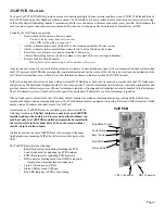
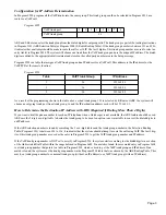
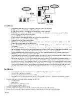
Plug the VoIP PCB into slots 4-8 in the main system cabinet, slots 12-16 in the second cabinet, or slots 20-24 in the third cabinet.
Only 1 VoIP PCB can be installed in the first cabinet, 2 VoIP PCBs each can be installed in the second and third cabinets.
8.
Connect the cable from the switching hub to the CN10 connector on the VoIP PCB using a CAT 5 cable.
9.
Set the run/block switch UP.
Before proceeding to Step 10, wait 30 seconds and verify that the LED starts to flash. This indicates that the board is
operating normally.
10. Replace the front cover and tighten the two front panel retaining screws.
11. Program the system with all the required VoIP options.
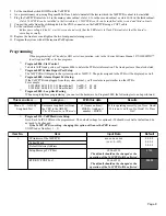
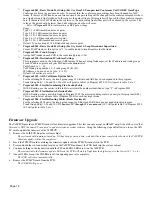
Programming
When programming VoIP trunks for DID or tie line operation, refer to the i-Series Software Manual, P/N 92000SWG**,
for all required DID or tie line programs.
➻
Program 0006 - Slot Control
To delete VoIP trunk ports, use Program 0006 to delete the PCB slot information. The trunk ports are then also deleted.
➻
Program 0007 System Report Port Setup
The VoIP PCB will display in the system reports as VoIPU-T. The ports assigned to the PCB will be displayed as well.
➻
Program 0008 - Alarm Report Port Setup
If the VoIP PCB is unplugged from the system cabinet, you
’
ll see alarm report similar to other PCBs.
For example:
0102 ERR 04/05/02 19:15 Board Install VoIPU-T 05 00
0102 REC 04/05/02 19:15 Board Install VoIPU-T 05 00
➻
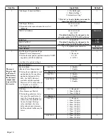
Program 0009 - Loop Back Testing
When using telephone programming, you can test the hardware. In Program 0009, the following test can be performed.
➻
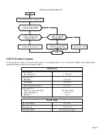
Program 0153 - VoIP Hardware Setup
Note: Each VoIPU PCB must be programmed. The default settings for options 4-20 should work well at default and do
not need to be changed.
If the VoIPU PCB is working, changing this option will cause the PCB to reset.
VOIPU Index Number ( 1 – 5 ).
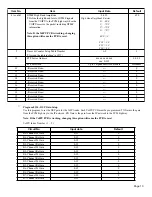
This menu item . . .
Lets you . . .
With this data
Results
Menu 11 — ADLSC
Loopback Test
Perform a loop back test from
the CEU to the ADLSC.
The PCB must be in NT mode.
11 (for menu item) +
HOLD + trunk port
HOLD.
If it is operating correctly, you
’
ll see: Good!
If it is not, you
’
ll see: No Good! Or Time
Out!
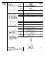
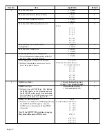
Item No.
Item
Input Data
Default
1
IP Address of the VoIP PCB
xxx.xxx.xxx.xxx
(xxx = 0-255)
0.0.0.0
0.0.0.0
0.0.0.0
Subnet Mask
Default Gateway Address
Setup Message TCP Port
1024-65535
The default should not be changed or the
operation of the VoIP PCB will be affected.
1720
RTP/RTCP UDP Port
1024-65518
The default should not be changed or the
operation of the VoIP PCB will be affected.
10020