3
This side faces the
front of the display.
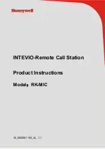
Optional Mounting Brackets:
Extended Height Bracket for 24” and 26” Radiance Displays:
Each step bracket is stamped with a part number (P/N). For
Radiance 24”
and
26”
displays, select the
extended height bracket P/N 20C0
901
. Replace the left hand mounting screws with 2 of the provided
mounting screws. Do not tighten them. Remove the two right hand screws from the VESA mount . With
the side stamped FRONT facing the front of the display, slide the step bracket between the VESA mount
and the back of the display until notches labeled for the display you are working with fit over the two left
hand screws. Replace the right hand screws with the screws provided and tighten all screws. With the flat
surface of a ZeroWire G2 Rx or Tx module facing the front of the display, align the slot on the bottom of the
module with the top of the bracket and push the module down on the bracket until the module seats.
Figure 1 shows the completed assembly.
Figure 1
Summary of Contents for 90T2071
Page 1: ...High Definition Wireless Video System User manual E n g l i s h ZeroWire G2 ...
Page 2: ......
Page 4: ......
Page 7: ...iii and 2007 47 EC ...
Page 27: ...20 ...
Page 28: ...21 ...
Page 29: ...0 01 0 12 0 12 0 23 0 1 0 38 0 38 0 73 1 1 2 1 2 2 3 10 3 8 3 8 7 3 100 12 12 23 22 ...
Page 30: ......
Page 31: ......