NCR INVENCO Retrofit G6 Plus InvencoLink GVR... Installation Manual Download Page 15


Document Number 

DCV-00202 

Date Released 

Oct. 2016 

Revision Number/Security level 

R01 S2 

Retrofit G6+InvencoLink GVR Advantage (US) Installation Guide 


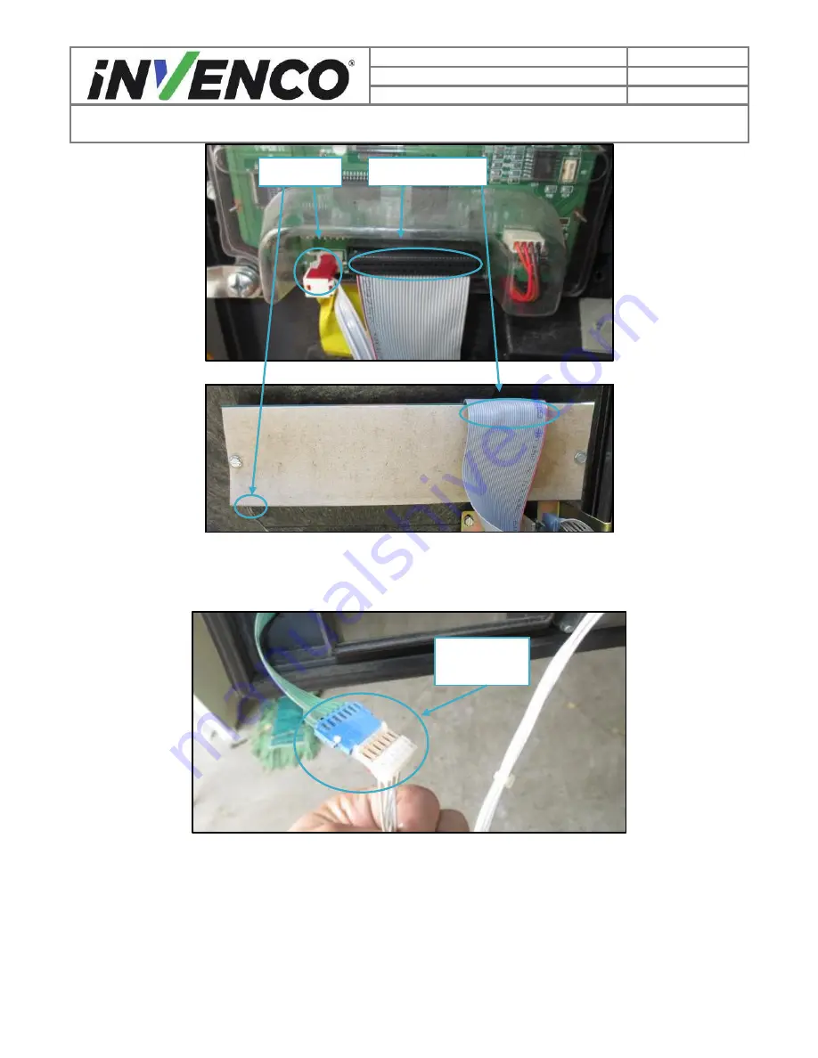
“Monochrome Display” 


“Single-Line Display” – Note: the grey cover can be left in place 

Fig. 1.4 

– Unplug backlight and display cables. 

3)

  Unplug the Handicap Assistance option cable if it is present. (Fig. 1.5) 


Fig. 1.5- Unplug handicap assistance cable 

4)

  Unplug the user keypad harnesses if it is present. (Fig. 1.6) 

Display Cable 

Backlight 

Cable 

Handicap 

Assistance 

Cable 

Summary of Contents for INVENCO Retrofit G6 Plus InvencoLink GVR...

Page 1: ...INSTALLATION INSTRUCTIONS NCR OPTIC 5 for GVR Advantage Release 1 0 497 0513340 Issue B...

Page 2: ...00202 Date Released Oct 2016 Revision Number Security level R01 S2 Retrofit G6 InvencoLink GVR Advantage US Installation Guide Retrofit G6 InvencoLink GVR Advantage US Installation Guide Kit Part Num...

Page 3: ...ved side specific BOM and added reference to InvencoLink PreInstallation to align the installation process with customer supply chain operation Added gasket replacement Added replacement lock latch de...

Page 4: ...7 2 6 Follow the Regulations 8 2 7 Replacement Parts 8 3 Safety Symbols and Terminology 8 3 1 Prevent Explosions and Fires 8 3 1 1 No Open Flames 9 3 1 2 No Sparks No Smoking 9 3 1 3 Working Alone 9 3...

Page 5: ...Retrofit Kit Part Number 6009 0008 8801 InvencoLink Converter before installation into the dispenser The process is covered in 4 2 Pre Installation Procedure of this instruction by reference to the i...

Page 6: ...s Unpack the Retro Fit Kit and check that all of the parts listed below are present G6 OPT IP0065 Mounted on RFK Door MP0550 PSU Plate with cables EZ0408 Cable Kit IA0029 Comprising clockwise from top...

Page 7: ...on Number Security level R01 S2 Retrofit G6 InvencoLink GVR Advantage US Installation Guide Sundry Parts Side One Comprising 2 MS0143 6 32 x machine screws 1 MN0032 3 4 Nut for the door lock 2 MF0046...

Page 8: ...these should they be required Locate the switch or circuit breakers that shut off all power to all fuelling equipment and dispensing devices 2 3 Total Electrical Shut Off Before Access Any procedure r...

Page 9: ...ol is used in this manual and on warning labels to alert you to a precaution which must be followed to prevent potential personal safety hazard Obey safety directives that follow this symbol to avoid...

Page 10: ...th this requirement refer to information in the relevant manual and OSHA documentation 3 1 4 Working with Electricity Safety Ensure that you use safe and established practices in working with electric...

Page 11: ...els of the G6 OPT incorporate a barcode reader The barcode reader incorporates a laser aiming system The Laser has a Class 2 output power to IEC 60825 1 2007 ANSI Z136 1 CAUTION LASER RADIATION DO NOT...

Page 12: ...omponents including The CRIND Panel Door with components card reader display etc The printer The T19501 Gx Monochrome display CPU board or other installed screens The CRIND Rack Assembly with wire ass...

Page 13: ...the bottom edge of the main door Depending on the model and dispenser setup there could be between two to four bolts to remove The bolts should be captive but may fall out Do not discard these bolts F...

Page 14: ...or and open it Fig 1 2b Unlock both option doors Narrow 6 Unplug all components on options door 1 Remove or unfasten any cord restraints that may be present on the options door Fig 1 3 Fig 1 3 Unfaste...

Page 15: ...nochrome Display Single Line Display Note the grey cover can be left in place Fig 1 4 Unplug backlight and display cables 3 Unplug the Handicap Assistance option cable if it is present Fig 1 5 Fig 1 5...

Page 16: ...mber Security level R01 S2 Retrofit G6 InvencoLink GVR Advantage US Installation Guide Fig 1 6 Unplug user keypad harnesses 5 Unplug the soft key cables Fig 1 7 Fig 1 7 Unplug Soft key cables 6 Unplug...

Page 17: ...penser cavity to set them out of the way 8 Remove the factory lock assembly on the CRIND options door Note The factory lock will be kept and reused during the installation process of the new OPT kit D...

Page 18: ...9b Latch set screw and lock washer 2 Depending on the lock mounting use one of the following to undo the lock i Using a large flathead screwdriver pry off and discard the snap collar from the lock as...

Page 19: ...the front of the options door Be careful not to pull out the lock cylinder from the cylinder housing Fig 1 9e Fig 1 9e lock cylinder and cylinder housing 4 Set the lock assembly aside It will be reus...

Page 20: ...level R01 S2 Retrofit G6 InvencoLink GVR Advantage US Installation Guide 9 Unlatch all the main door latches The Wide Frame has four latches the Narrow Frame has three latches Fig 1 10a b Wide Frame...

Page 21: ...11 Main door in its fully open position 11 To remove the left option door use a pair of needle nose pliers to grasp the hinge pin and lift it upwards and pull it up through the top of the door until...

Page 22: ...16 Revision Number Security level R01 S2 Retrofit G6 InvencoLink GVR Advantage US Installation Guide Fig 1 12a Firmly grasp the hinge pin with needle nose pliers Fig 1 12b Remove hinge pin and keep Do...

Page 23: ...rmer OR from an AC voltage bus cable via a universal comm and power cable assembly Identify which setup the dispenser chosen for installation currently uses and follow one of the two following procedu...

Page 24: ...ation of transformer as viewed from A Side 2 Unplug the 6 pin CRIND power terminal wire harness Fig 1 13b Fig 1 13b Unplug the CRIND power cable 3 Unplug any peripheral power cables that may be connec...

Page 25: ...harness typically labeled J412 connected to the CRIND board assembly and unscrew the ground wire attached to it if present Fig 1 13c d Fig 1 13c Unplug J412 harness Fig 1 13d Unscrew ground wire 5 Pr...

Page 26: ...the CRIND board assembly The connector is typically labeled J412 in a newer pump or J402 in an older pump Fig 1 14b c 3 Unplug the 3 wire AC wire harness that is plugged into the voltage bus cable The...

Page 27: ...4d Unscrew ground wire 13 Unplug and remove the T19501 Gx Monochrome Display Board from the board cage if it is present Note that it may not be the top board in the cage as shown depending on other pu...

Page 28: ...of the dispenser open the right hand door using the same techniques outlined in steps 4 5 above From that side unplug the printer s data and power cables Remove or unfasten any cord restraints that m...

Page 29: ...wire assemblies to front of dispenser 3 Pull the CRIND rack assembly forward towards the front of the dispenser until it stops While tilting it down lift up on the rack assembly to remove it from the...

Page 30: ...8b Lift CRIND rack up and pull out 4 Set the entire CRIND rack assembly aside 18 Remove printers 1 Remove the clip on ground terminal Fig 1 19 Fig 1 19 Remove clip on ground wire 2 Using a 3 8 socket...

Page 31: ...ng each rail in position Unscrew the nuts completely and remove the rails Fig 1 21 Remove two nuts on each rail 20 With the exception of the main door retaining bolts removed in step 4 the lock remove...

Page 32: ...he previous equipment to the MP0550 RFK Door a Insert the Lock Cylinder and Housing from the outside Orient it so that when the key is inserted its teeth will be towards the edge of the door Fig 2 1 U...

Page 33: ...ld be downward when unlocked Fig 2 4 Unlocked position key vertical Latch downward 4 2 2 Replace the Gasket on the Pump Door When the CRIND Option Door is replaced with the NCR Invenco RFK Door a new...

Page 34: ...ve residue b Use the flat bladed scraper or the putty knife on stubborn areas taking care not to gouge the plastic surface WARNING Do not flood the area being cleaned with a direct spray of sticky res...

Page 35: ...or Side Two i e the second side you MUST have Side One i e the first side already installed and you may then proceed to 4 3 Installation Procedure For Side One i e the first side select the PSU Plate...

Page 36: ...ide you re working on 1 Install the pre assembled EZ0408 PSU plate into the pump in the cavity behind where the left hand CRIND door was For Side One this is the PSU Plate Assembly that has just had t...

Page 37: ...ket ii Plug the EK0131 YELLOW cable into the LAN 1 socket b For Side Two the converter will be on the plate on the other side of the dispenser and you should run the two cables under any central elect...

Page 38: ...o prevent it swinging during the next steps Note The lock is likely to be quite stiff because the seals are new 7 Remove the screws on the cable retention bracket on the OPT keep the screws CAUTION Du...

Page 39: ...31 YELLOW patch cables into the correct sockets on the OPT The port numbers on the InvencoLink for each cable e g LAN 1 RS232 1 must match the side you re working on e g Side One Fig 3 7 Patch Cable c...

Page 40: ...nection and cable retention bracket 10 Connect the earth cable from the RFK Door onto the EZ0408 PSU Plate earth stud Remove the nut from the earth stud slip the ring terminal over the stud then re in...

Page 41: ...Datacom converter Fig 3 12 Cables retained in cavity near pump door clasp 13 Plug the single connector end of the EK0124 Mains cable into the mains connector on the EZ0408 PSU Plate Fig 3 13 Plug EK01...

Page 42: ...3 15 Routing EK0124 EK0125 For Side One EK0124 is supplied with a dummy plug for safety in some installations The plug looks like this 16 For Side One a For a newer pump remove and discard the dummy...

Page 43: ...nstallation repeat steps 1 13 15 17 19 for Side Two 20 Secure the EK0124 and EK0125 cables to existing pump wiring in the lower cabinet where possible using cable ties Ensure the cables will not be sn...

Page 44: ...omplete 5 First Power Up Once the installation is complete and the wiring is certified if necessary power may be applied The G6 OPT takes a couple of minutes to complete its start up phase during whic...

Page 45: ...ion Insert roll in place the paper tension flap is spring loaded so you will need to apply some pressure Insert the spindle through the middle of the roll to hold in place 3 Insert the cut edge of the...

Page 46: ...ision Number Security level R01 S2 Retrofit G6 InvencoLink GVR Advantage US Installation Guide 6 Feed the paper through the terminal until it appears at the paper exit chute Cut the paper using both f...

Reviews: