Chapter 5: Service
5-5
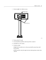
1.
Remove
only
two
cabinet
screws.
14540
(2) Bracket Screws
(2) Cabinet Screws
14540
2.
Remove
the
PC
board.
3.
Disconnect
the
board
from
the
24
‐
position
connector.
4.
Reinstall
a
new
PC
board.
5.
Route
the
cable.
VFD:
Pull
the
cable
down
so
the
strain
relief
becomes
flush
with
the
housing.
LCD:
Route
the
cable
through
the
strain
relief
guides
located
in
the
cabinet.
Summary of Contents for 5972-1000
Page 1: ...NCR 5972 2x20 Customer Display Release 2 0 User s Guide BD20 1372 A Issue F...
Page 4: ...0 2 Chapter 1 Introduction...
Page 10: ...0 8 Chapter 1 Introduction...
Page 14: ...1 4 Chapter 1 Introduction...
Page 24: ...2 10 Chapter 2 Site Preparation...
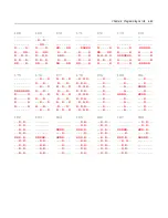
Page 57: ...Chapter 4 Programming Set Up 4 27 245 246 247 248 249 250 251 252 253 254 255...
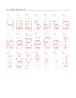
Page 70: ...4 40 Chapter 4 Programming Set Up 252 253 254 255...
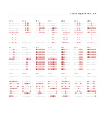
Page 83: ...Chapter 4 Programming Set Up 4 53 252 253 254 255...

