

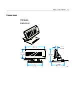


Chapter 2: Site Preparation
2-7
Electrical Environment
VFD AC Power Requirements
•
120
VAC,
60
Hz
(US,
Canada,
and
others)
via
a
wall
mount
power
supply
•
90
‐
264
VAC,
50
‐
60
Hz
via
a
Universal
Input
power
supply
VFD DC Power Requirements
•
10
VDC
to
14VDC
(0.8
A
max.
at
12VDC)
LCD AC Power Requirements
•
No
AC
P/S
available.
The
LCD
receives
power
from
the
host
via
a
powered
RS
‐
232
connector.
LCD DC Power Requirements
•
10.6VDC
to
13VDC
(160mA
max
at
12VDC)
Operational Environment
System Configuration
The
VFD
communicates
with
the
host
via
the
parallel
port
or
EIA
‐
232
serial
port
of
the
host.
Both
interfaces
are
active
at
the
same
time.
The
display
does
not
need
to
know
which
cable
it
is
connected
to.
However,
both
interface
cables
cannot
be
connected
to
the
unit
at
the
same
time.
The
LCD
communicates
with
the
host
via
the
serial
port
only.
Summary of Contents for 5972-1000
Page 1: ...NCR 5972 2x20 Customer Display Release 2 0 User s Guide BD20 1372 A Issue F...
Page 4: ...0 2 Chapter 1 Introduction...
Page 10: ...0 8 Chapter 1 Introduction...
Page 14: ...1 4 Chapter 1 Introduction...
Page 24: ...2 10 Chapter 2 Site Preparation...
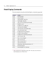
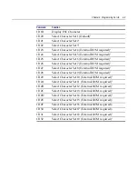
Page 57: ...Chapter 4 Programming Set Up 4 27 245 246 247 248 249 250 251 252 253 254 255...
Page 70: ...4 40 Chapter 4 Programming Set Up 252 253 254 255...
Page 83: ...Chapter 4 Programming Set Up 4 53 252 253 254 255...