background image


                                1


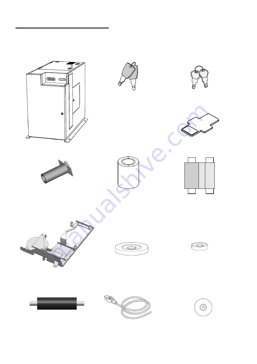
Contents of the package 


The package contains the following items. 

(Please contact your dealer if you cannot find anything.) 


Cover key (2 pieces x 3)                Cassette key (2 pieces x 2) 


Main Body                                                                                                        Weight (6 pieces) 


Reel hardware for tipper                   Tipper Foil              Thermal Transfer Ribbon 

(with paper core) 


Indent Cassette                        Indent film                 Indent film empty core 


Cleaning Roller                 


 Power cable            CD (Operation Manual (pdf)) 


.

Summary of Contents for Advantage M8

Page 1: ...Advantage M8 Operation Manual MANUAL NO Advantage M8 UM 153 Card Printer Embosser NBS Technologies Inc ...

Page 2: ...ever do this Be sure to follow instructions Product Handling Used only in non tropical conditions Operating environment Temperature 10 to 32 degrees Celsius Humidity 20 to 65 R H non condensing Do not overload one electrical outlet by using a power strip and multi outlet adapter It may cause electric shock or fire Warning Do not disassemble or modify It may cause an electric shock or fire If it is...

Page 3: ...nits when you take out remaining card or conduct maintenance work It may cause an injury The Tipper Unit might be hot To reduce the risk of injury from the heat allow the Tipper Unit to cool before touching Warning Please take care not to get your hand or finger caught when you open and close the upper ...

Page 4: ...es when the host computer and this machine are turned off Do not insert the power plug into the outlet until the connection is completed LAN connector and USB connector are sensitive to ESD Connect these communication cables when the machine is powered off Avoid installing in a place with extremely high temperatures humidity or a place with rapid humidity changes It may cause condensation resultin...

Page 5: ... quality To carry a card it is recommended that it is held by its edges Do not put or store cards in a dusty place a place with high temperatures or near electric appliances that may emit a strong magnetic field such as a mobile phone and monitor It may cause deformation of cards or deletion of magnetic data Caution Do not bend the cards or damage the magnetic strip It may interfere with proper re...

Page 6: ...peration is subject to the following two conditions 1 This device may not cause interference 2 This device must accept any interference including interference that may cause undesired operation of the device L émetteur récepteur exempt de licence contenu dans le présent appareil est conforme aux CNR d Innovation Sciences et Développement économique Canada applicables aux appareils radio exempts de...

Page 7: ...Message 24 Error during standby 24 Consumable error 25 Error during operation 26 Error and warning during printing or encoding operation 28 Error Reset 30 Removing the card remaining in Input Hopper 30 Removing the card remaining in Main Transfer Unit 32 Removing the card remaining in Print Encode Unit 35 Removing the card remaining in Vertical Rotation Unit 39 Removing the card remaining in Carri...

Page 8: ...dealer if you cannot find anything Cover key 2 pieces x 3 Cassette key 2 pieces x 2 Main Body Weight 6 pieces Reel hardware for tipper Tipper Foil Thermal Transfer Ribbon with paper core Indent Cassette Indent film Indent film empty core Cleaning Roller Power cable CD Operation Manual pdf ...

Page 9: ...2 Name of Each Part Front Back Top Cover Right side door Front Cover Power Switch Main display Card Insertion Exit Slot LAN Connector AC Inlet USB Connector Circuit Breaker ...

Page 10: ...3 Inside of Front Cover Inside of Top Cover Print Encode Unit Tipper Unit Reject Stacker Unit Input Hopper Output Stacker Unit Hopper Cassettes Print Encode Unit display ...

Page 11: ...er unit to carry a card to the Vertical Rotation unit Emboss Unit and Tipper Unit to be called Carriage in this manual Emboss Unit Carriage Unit Main Transfer Unit Vertical Rotation unit Elevator part to be called Carrier in this manual ...

Page 12: ... 14 3 Connect the host computer and the main body with connection cable 4 Connect the power cord to the AC inlet and AC outlet 5 Install the ribbon according to the procedure Exchange of Thermal Transfer Ribbon on page 12 Communication connectors LAN USB are very sensitive to static electricity You should turn off the power before you connect or remove the cables on the rear side to protect the ma...

Page 13: ... display CV401 Front Front Cover Front Cover of the main body can only be opened by unlocking both the physical cover key and electrical lock For unlocking the electrical lock you need to connect a LAN cable and run application software Reference After unlocking the electrical lock the Front Cover must be opened promptly If the Front Cover is left closed for a while it will be locked by the electr...

Page 14: ...7 2 Pull out the Hopper Cassette from the main body 3 Open the Hopper cover by turning the Hopper cassette key clockwise Turn the hopper cassette key clockwise Open the Hopper Cover ...

Page 15: ...cards Please refer to the Illustration inside of the cassette to find card setting direction Placing the cards in an extremely skew or acute angle may interfere with proper card seating and cause card jams Set the cards on the sensor pin softly while keeping them horizontally If the edge of a card is out of the Gate it may cause card jams In this case please remove all cards from the cassette temp...

Page 16: ...m sticking to each other check that there is no foreign object in the input hopper then place the cards into the cassette If you see a card edge at the gate all cards must be taken out from the cassette and reseated again Caution Card comes out of the Gate Bad setting example NG Gate Card Good setting example OK Card is placed in cassette properly ...

Page 17: ... Cassette turn the power ON 3 When the buzzer starts beeping release the Indent Cassette 4 The IP address Subnet mask and Gateway will be displayed on the Main display scrolling every two seconds repeatedly Ixxx xxx xxx xxx Displayed IP address Sxxx xxx xxx xxx Displayed Subnet mask Gxxx xxx xxx xxx Displayed Gateway While getting an IP address from DHCP server the Main display shows as follow Ple...

Page 18: ...ion Exit Slot 7 Error card will be transferred to the Reject Box If any error is detected during initialization an error message is indicated on the Main display Please refer to Error message in this manual about the details and its measures Reference Do not insert a card or cover the Card Insertion Exit Slot during the operation If you open the Front cover Side door or the Top cover during the op...

Page 19: ...er will beep and the following error message will be indicated on the Main display CV402 Top Side 2 Push the Print Encode Unit Cover Open Button to open the cover 3 Detach the Thermal Transfer Ribbon from the Print Encode Unit Open Print Encode Unit cover Print Encode Unit Print Encode Unit Cover Open Button Open Top Cover Turn this key clockwise ...

Page 20: ...d then lock the Top Cover key Be sure to push the RIBBON SET button after installing a new ribbon Otherwise a print failure will occur Be sure to remove the slack of the Thermal Transfer Ribbon before closing the cover The slack will adversely affect the print quality Caution RIBBON SET button Thermal Transfer Ribbon Unused side Used side Turn the unused side of the ribbon counter clockwise to rem...

Page 21: ...urning the key clockwise 2 Grab the handle of the Tipper Unit to pull out from the main body There is a very high temperature part in the Tipper Unit Make sure to grab the handle to avoid a burn when you pull up the Tipper Unit Caution Handle Open Top Cover Turn this key clockwise ...

Page 22: ...per Foil from the reel hardware then Install the empty paper core to it Confirm there is no gap between the paper core and the flange of the reel hardware Be sure to exchange the Tipper Foil after it is sufficiently cooled down Caution Paper Core Unreel Flange Knob Used Tipper Foil Reel Flange Knob Reel Hardware Paper Core Confirm there is no gap between the paper core and the Flange of reel hardw...

Page 23: ...to the Unreel flange while pulling the knob in the direction of the arrow 7 Pull out the Tipper foil and fix the edge of the foil to the paper core with an adhesive tape Turn the Reel flange knob counter clockwise approximately one turn to wind the foil on the reel New Tipper Foil Unreel Flange Turn the knob one rotation Fix the foil to the Paper Core Knob Fit this hole to the pin of Tipper Unit ...

Page 24: ...17 8 Gently slide the tipper Unit into the tipper holder along the guide rail 9 Close the Top Cover and lock with the key Guide Fin Slide in the Tipper Unit along the guide rail slowly ...

Page 25: ...lockwise to open If carriage disturbs your access push it to the right side 2 Release lock by pushing the lock lever with holding the Indent Cassette handle and remove Indent Cassette upward and forward from the Emboss Unit Emboss Unit Carriage Unit Lock lever Handle Indent Cassette ...

Page 26: ... film according to the guidance figure for Film Setting Fix the edge of the film onto the Empty Core with the fixing tape At this time the film should not lie off the core largely 6 Turn the empty core three times counter clockwise to remove the slack of the indent film Close the Film Guide and fix the thumb screw Used film Empty Core Film Guide Thumb screw Used film New film Empty Core Guidance f...

Page 27: ...n the Right side door 8 After attaching the cassette check that the film has no slack Close the Right side door and lock with the key Be sure to remove the slack of the Indent Film before installing the Indent Cassette The slack may adversely affect the print quality Before installing the halfway used film again be sure to wind the used part completely Caution Guide Hole Guide Shaft Push down the ...

Page 28: ...r by turning the key clockwise When the Front Cover is opened the buzzer will beep and the following error message will be indicated on the Main display CV401 Front 2 Pick up the cards from the Output Stacker 3 Close the Front cover and then lock the Front Cover with the key Output Stacker Unit Open Front Cover Turn this key clockwise ...

Page 29: ...r by turning the key clockwise When the Front Cover is opened the buzzer will beep and the following error message will be indicated on the Main display CV401 Front 2 Pick up the cards from the Reject Stacker 3 Close the Front cover and then lock the Front Cover with the key Reject Stacker Unit Open Front Cover Turn this key clockwise ...

Page 30: ... minutes When the machine has been kept on standby for 30 minutes or more it shifts to the Eco mode iv 60 minutes When the machine has been kept on standby for 60 minutes or more it shifts to the Eco mode Factory default setting is No for both of Hopper and Motor 3 During Eco mode the following message will be indicated on the Main display Eco mode Tipper Tipper is in Eco mode Eco mode Motor Motor...

Page 31: ...Error Message Details and Countermeasures CV301 Lock error Detect electric lock anomaly on Front Cover CV302 Unlock err Detect electric unlock anomaly on Front Cover CV401 Front Detect Front Cover is open during standby Close the cover to clear the error CV402 Top Side Detect Top Right side door is open during waiting Close the cover to reset the error CV512 Sensor err Detect cover sensor anomaly ...

Page 32: ...opper 5 IH106 No card 6 No card in Hopper 6 IH107 No card 7 No card in Hopper 7 IH108 No card 8 No card in Hopper 8 IH109 No card 9 No card in Hopper 9 IH110 No card 10 No card in Hopper 10 IH111 No card 11 No card in Hopper 11 IH112 No card 12 No card in Hopper 12 IH113 No card 13 No card in Hopper 13 IH114 No card 14 No card in Hopper 14 IH115 No card 15 No card in Hopper 15 IH121 No cst 1 Hoppe...

Page 33: ...d remaining on carriage Power OFF and remove the card CM501 Unknown Receive unknown commands Make sure host PC and this product are connected correctly by LAN or USB CM502 Sequence Detect sequence error Make sure host PC and this product are connected correctly by LAN or USB CM503 Parameter Detect parameter error Make sure host PC and this product are connected correctly by LAN or USB CM513 Receiv...

Page 34: ...ot fall inside the machine SY501 Not init Card issuance command was sent before initialization Initialize the machine from host PC SY904 FRAM error Detect FRAM for data storage error Power OFF and ON TP211 Press err Detect an error during Tipper foil pressing operation Power OFF and ON TP301 HP err Detect an error during searching home position Power OFF and ON TP401 Wup err Heater temperature doe...

Page 35: ...sfer Ribbon has not run out 4 Card Code Message Details and Countermeasures 17 IC Module Up Down Error IC Content module position error occurs Repair service is required Contact your distributor 50 Changer Module Response Timeout Flipper communication error occurs Turn the power OFF and remove the card from Print Encode Unit turn the power ON 51 Changer Module Transmission Timeout Flipper communic...

Page 36: ...unication failed Make sure whether the card is not set in the wrong direction 33 Card Eject Error Flipper module communication failed Turn the power OFF and remove the card from Print Encode Unit turn the power ON 34 Card Input Timeout The card input is interrupted Make sure whether any cards are not jammed in the path from the Input Hopper to Print Encode Unit 2 Ribbon Code Message Details and Co...

Page 37: ...cover by the application software Then open the Front cover by turning the key clockwise 2 Remove the Hopper Cassette that has the remaining card 3 Remove the card from the rear side of the Hopper Cassette Remaining Card Hopper Cassette Pull to remove the card Turn this key clockwise Hopper Cassettes ...

Page 38: ...ing its key clockwise Remove all weight and cards and pull out the remaining card from the Hopper 4 Close the Hopper Cover and install the Hopper Cassette to the machine Close the Front Cover and lock the Key by turning it counterclockwise Remove the remaining card from the front Remaining card Hopper Cover ...

Page 39: ...nsfer Unit 1 Turn the power OFF and open the Right side door by turning the key clockwise 2 Check if any cards are remaining in the Carrier of the Main Transfer Unit Carrier of the Main Transfer Unit Turn this key clockwise Open Right side door ...

Page 40: ...the Knob X to carry the card toward the Carrier When you cannot access the Carrier grip Knob Z and pull the Carrier forward Turn the Knob X counter clockwise to carry the card to the left side Turn the Knob X clockwise to carry the card to the right side ...

Page 41: ...t Unit While holding the Knob Y turn the Knob X clockwise to bring out the card from the Carrier Pull out the card by hand 4 Close the Right side door and lock with the key Knob Y Knob X Vertical Rotation Unit Indent Unit Pull out the card from the Carrier by hand Hold the Carrier while removing the card ...

Page 42: ...urning the key clockwise Open Top Cover by turning the key clockwise 2 Push down the button to open the Print Encode Unit cover Open Top Cover Turn this key clockwise Open Right side door Turn this key clockwise Open Print Encode Unit cover Print Encode Unit cover Print Encode Unit Cover Open Button ...

Page 43: ...ard toward the Main Transfer Unit by turning Knob counterclockwise 5 Pull out the card from the left side of the Print Encode Unit Transfer the remaining card to Main Transfer Unit Remaining card Turning knob counterclockwise Remaining Card Pull out the card from the Print Encode Unit ...

Page 44: ...nd then lock the Top Cover with the key 9 Close the Right side door and then lock the Right side door with the key 10 Turn the power ON and initialize the machine 11 Open the Top Cover by turning the key clockwise while power ON Ignore buzzer beeping and the following error message in the Main display to proceed next step CV402 T op Side Thermal Transfer Ribbon Turn the unused side of the ribbon c...

Page 45: ...er with the key Do not forget to push RIBBON SET button after installing a new ribbon Otherwise a print failure will occur Be sure to remove the slack of the Thermal Transfer Ribbon before closing the cover The slack will adversely affect the print quality Caution RIBBON SET button ...

Page 46: ...pen the Right side door by turning the key clockwise 2 Remove the remaining card from the right side of the Vertical Rotation Unit 3 Close Right side door and then lock the Right side door with the key Open Right side door Turn this key clockwise Remaining Card Vertical Rotation Unit ...

Page 47: ...Unit stops In the case when the Carriage Unit stops around the Tipper Unit wait more than one hour until the Tipper Unit is cooled down After the Tipper Unit has completely cooled down proceed to the step 3 Open Top Cover Turn this key clockwise Tipper Unit If the Carriage Unit stops at the upper right position wait until the Tipper unit is cooled down ...

Page 48: ...n needle lever is opened 4 Close Top Cover and lock by the key Carriage Unit Remaining Card Open Needle Lever by pushing the shaft Needle Lever Shaft Push the shaft backward with holding the card Tipper Unit has a very high temperature part If you make the above process turn off the power and wait at least 1 hour until the Unit has been completely cooled down to prevent your arms or hands from get...

Page 49: ...maining between emboss type in Emboss Unit In the case when the card is remaining in Emboss Unit and held by Needle lever of Carriage Unit remove the card from the Carriage by opening the needle lever as shown on page 40 in this manual Emboss Unit Open Right side door Turn this key clockwise Emboss Unit Remaining Card Open Top Cover Turn this key clockwise Remaining Card Emboss Type ...

Page 50: ... are not aligned each other it may damage the Emboss type When the Emboss Type is not aligned to the Emboss Pin rotate the Emboss Drum to set the Emboss Type to the right position Emboss Drum Emboss Unit Emboss Type Emboss Pin Emboss Type and Emboss Pin are aligned ...

Page 51: ... the Right side door and then lock the Right side door with the key There is a high temperature area in the Tipper Unit To perform the above process turn off the power and wait at least 1 hour until the Unit has been completely cooled down to prevent your arms or hands from getting burned When turning the Crankshaft make sure the Emboss type is aligned to the Emboss pin In the case when the emboss...

Page 52: ...rd was not ejected completely from the Card Insertion Exit Slot pull out the card by hand 2 Remove the card according to the procedure Remove the card in Main Transfer Unit on page 30 when you cannot pull the card out by hand Card Insertion Exit Slot Remaining Card Pull ...

Page 53: ... turning the key clockwise during the power on and then open the Top Cover The buzzer will beep and the following error message will be indicated on the Main display CV402 Top Side 2 Push the Print Encode Unit Cover Open Button to open the cover Open Top Cover Turn this key clockwise Print Encode Unit Cover Open Button Thermal Print Head Open Print Encode Unit cover Print Encode Unit ...

Page 54: ... slack 5 Close the Print Encode Unit cover until it clicks Recap the pen after cleaning for reuse Reference Before closing the Print Encode Unit cover make sure the alcohol on the Thermal Print Head has evaporated Caution Thermal Transfer Ribbon Unused side Used side Wind the ribbon Do not touch the Thermal Print Head with your fingers Caution ...

Page 55: ...r with the key Do not forget to push RIBBON SET button after installing a new ribbon Otherwise a print failure will occur Be sure to remove the slack of the Thermal Transfer Ribbon before closing the cover The slack will adversely affect the print quality Caution RIBBON SET button ...

Page 56: ...r when replacing the Thermal Transfer Ribbon 1 Unlock the Top Cover by turning the key clockwise during the power on and then open the Top Cover The buzzer will beep and the following error message will be indicated on the Main display CV402 Top Side 2 Push the Print Encode Unit Cover Open Button to open the cover Open Top Cover Turn this key clockwise Open Print Encode Unit cover Print Encode Uni...

Page 57: ...int Encode Unit 4 Remove the Cleaning roller from the Print Encode Unit 5 Wash the Cleaning roller with running water 6 Install the Cleaning roller to Print Encode Unit after drying Cleaning roller Detach this side first to take out the Cleaning Roller ...

Page 58: ...n lock the top cover with the key RIBBON SET button Turn unused side of the ribbon counter clockwise to remove the slack Thermal Transfer Ribbon Unused side Used side Do not forget to push RIBBON SET button after installing a new ribbon Otherwise a print failure will occur Be sure to remove the slack of the Thermal Transfer Ribbon before closing the cover The slack will adversely affect the print ...

Page 59: ...52 Cleaning Card transfer rollers 1 Turn the power OFF and open the Right side door by turning the key clockwise Main Transfer Unit Vertical Rotation Unit Open Right side door Turn this key clockwise ...

Page 60: ...e turning the knob Use a waste cloth or a cotton swab absorbed with Ethanol 3 Clean the Card transfer rollers on the Vertical Rotation Unit Clean the Drive Roller and the three Passive Rollers while turning the white gear Use a waste cloth or a cotton swab absorbed with Ethanol Knob Passive Rollers Drive Rollers Drive Roller Gear Passive Roller ...

Page 61: ...rds Card Presence Detection Out of Card detection Manual insert mode Available Out Stacker Output Stacker Capacity Approximately 20 cards Card presence detection Card full detection Rejected Cards Reject stacker capacity Approximately 25 cards Card presence detection Card full detection Card Counter Resettable Software counter Non resettable Mechanical counter Dimensions 456mm W x 658mm H x 771mm ...

Page 62: ...t printing character type 10 characters 0 to 9 OCR B 14CPI Option Reverse italic Indent Film Detection Film end detection Possible Indent area Lower limit 15 2 from lower end of the card to character center line Upper limit 37 8 from lower end of the card to character center line Left limit 3 7 from left end of the card to character center line Right limit 81 3 from left end of the card to charact...

Page 63: ...perature 18 to 28 degrees Celsius Humidity 40 to 65 R H Operating environment Temperature 10 to 32 degrees Celsius Humidity 20 to 65 R H 0 20 40 60 80 100 0 C 10 C 20 C 30 C 40 C Operating environment Guaranteed accuracy environmen Temperature Humidity 900 ...

Page 64: ...57 Specifications are subject to change without notice Advantage M8 Operation Manual Advantage M8 UM 153 June 7 2018 4rd edition Sales origin NBS Technologies Inc Manufacturer NBS Card Corporation ...

Reviews: