background image

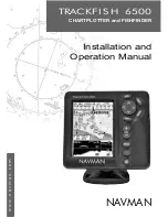
TRACKFISH 6500 

 Installation and Operation Manual

4

NAVMAN 

8 Sonar fishfinding: Introduction ........................................................................................................... 31

8-1 Using the TRACKFISH . . . . . . . . . . . . . . . . . . . . . . . . . . . . . . . . . . . . . . . . . . . . . . . . . . . . . . . . . . . . 31
8-2 Interpreting the display . . . . . . . . . . . . . . . . . . . . . . . . . . . . . . . . . . . . . . . . . . . . . . . . . . . . . . . . . .32
8-3 Single and Dual frequency fishfinding . . . . . . . . . . . . . . . . . . . . . . . . . . . . . . . . . . . . . . . . . . .34
8-4 Fish detection and display . . . . . . . . . . . . . . . . . . . . . . . . . . . . . . . . . . . . . . . . . . . . . . . . . . . . . . .37
8-5 Range . . . . . . . . . . . . . . . . . . . . . . . . . . . . . . . . . . . . . . . . . . . . . . . . . . . . . . . . . . . . . . . . . . . . . . . . . . .38
8-6 Gain and threshold . . . . . . . . . . . . . . . . . . . . . . . . . . . . . . . . . . . . . . . . . . . . . . . . . . . . . . . . . . . . . .39

9 Sonar fishfinding: Displays ..................................................................................................................40

9-1 Sonar history display  - no split  . . . . . . . . . . . . . . . . . . . . . . . . . . . . . . . . . . . . . . . . . . . . . . . . . .40
9-2 Sonar Zoom display . . . . . . . . . . . . . . . . . . . . . . . . . . . . . . . . . . . . . . . . . . . . . . . . . . . . . . . . . . . . . 41
9-3 Sonar Bottom display . . . . . . . . . . . . . . . . . . . . . . . . . . . . . . . . . . . . . . . . . . . . . . . . . . . . . . . . . . . . 41
9-4 Sonar 50/200 display . . . . . . . . . . . . . . . . . . . . . . . . . . . . . . . . . . . . . . . . . . . . . . . . . . . . . . . . . . . .42
9-5  Sonar A-Scope display . . . . . . . . . . . . . . . . . . . . . . . . . . . . . . . . . . . . . . . . . . . . . . . . . . . . . . . . . .42

10 Gauges display ...................................................................................................................................44

11 Data display .......................................................................................................................................45

12 Fuel functions and display ..................................................................................................................46

12-1 When you add or remove fuel . . . . . . . . . . . . . . . . . . . . . . . . . . . . . . . . . . . . . . . . . . . . . . . . . .46
12-2 Fuel display  . . . . . . . . . . . . . . . . . . . . . . . . . . . . . . . . . . . . . . . . . . . . . . . . . . . . . . . . . . . . . . . . . . . .47
12-3 Fuel consumption curves  . . . . . . . . . . . . . . . . . . . . . . . . . . . . . . . . . . . . . . . . . . . . . . . . . . . . . .48

13 Tides display ......................................................................................................................................50

14 User card display ................................................................................................................................ 51

15 DSC/Buddy track displays ...................................................................................................................52

15-1 The displays . . . . . . . . . . . . . . . . . . . . . . . . . . . . . . . . . . . . . . . . . . . . . . . . . . . . . . . . . . . . . . . . . . . .53
15-2 Using the displays . . . . . . . . . . . . . . . . . . . . . . . . . . . . . . . . . . . . . . . . . . . . . . . . . . . . . . . . . . . . . .54

16 About display ..................................................................................................................................... 55

17 Setting up the TRACKFISH ................................................................................................................... 55

17-1 Setup  > System . . . . . . . . . . . . . . . . . . . . . . . . . . . . . . . . . . . . . . . . . . . . . . . . . . . . . . . . . . . . . . . .57
17-2 Setup  > Chart  . . . . . . . . . . . . . . . . . . . . . . . . . . . . . . . . . . . . . . . . . . . . . . . . . . . . . . . . . . . . . . . . . .58
17-3 Setup > Sonar . . . . . . . . . . . . . . . . . . . . . . . . . . . . . . . . . . . . . . . . . . . . . . . . . . . . . . . . . . . . . . . . . . 61
17-4 Setup  > GPS  . . . . . . . . . . . . . . . . . . . . . . . . . . . . . . . . . . . . . . . . . . . . . . . . . . . . . . . . . . . . . . . . . . .62
17-5 Setup > Fuel  . . . . . . . . . . . . . . . . . . . . . . . . . . . . . . . . . . . . . . . . . . . . . . . . . . . . . . . . . . . . . . . . . . .62
Summary of Contents for TRACKFISH 6500

Page 1: ...w w w n a v m a n c o m TRACKF I S H 6500 CHARTPLOTTER and FISHFINDER Installation and Operation Manual NAVMAN...

Page 2: ...ful interference to radio or television reception which can be determined by turning the equipment off and on the user is encouraged to try to correct the interference by one or more of the following...

Page 3: ...ht and night mode 12 2 4 Man overboard MOB 12 2 5 Alarms 13 2 6 Simulate mode 13 2 7 The main displays 14 3Navigation Chart 18 3 1 Introduction to navigating 18 3 2 Chart display 21 3 3 Distance and b...

Page 4: ...lit 40 9 2 Sonar Zoom display 41 9 3 Sonar Bottom display 41 9 4 Sonar 50 200 display 42 9 5 Sonar A Scope display 42 10Gaugesdisplay 44 11Datadisplay 45 12Fuelfunctionsanddisplay 46 12 1 When you add...

Page 5: ...d Accessories 71 18 3 Installation The display unit 73 18 4 Installation Power data cable 74 18 5 Installation GPS antenna 75 18 6 Installation Sonar transducer 75 18 7 Installation Navman petrol gaso...

Page 6: ...display can be limited by many factors including the type of the transducers the location of the transducers and water conditions It is the user s responsibility to ensure the TRACKFISH transducers ar...

Page 7: ...r card Chart data Chart features built in world chart 3 2 Chart details 3 2 4 5 C MAP chart Tides at a port 13 C MAP chart Alarms Built in alarms 2 5 SmartCraft engine alarms 1 1 SmartCraft Boat data...

Page 8: ...amming cables and connectors Keep the transducer free of weed paint and debris Do not use a high pressure water blast on a speed sensor paddlewheel as it may damage the bearings Push the dust cover ov...

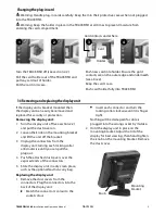
Page 9: ...urn the display unit off see section 2 2 and put the dust cover on 2 Loosen the knob on the mounting bracket and lift the unit off the bracket 3 Unplug the connectors from the display unit turning eac...

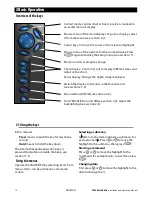
Page 10: ...display to the next in the favourites list see section 2 7 2 Man overboard MOB see section 2 4 Turn TRACKFISH on and o see section 2 2 adjust the backlighting see section 2 3 2 1 Using the keys In th...

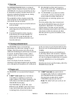
Page 11: ...wired for auto power press to turn the unit on If necessary adjust the display to be easy to read see section 2 3 Note If the TRACKFISH is not wired for auto power then the TRACKFISH does not record e...

Page 12: ...igation If the chart can not show the required small scale the TRACKFISH changes to plotter mode a white display with crosshatching and no chart details see section 17 2 3 The TRACKFISH sets the MOB w...

Page 13: ...ute and automatically displays different TRACKFISH functions To start and stop Simulate mode and for more information see section 17 14 In simulate mode Simulate or Demo flashes at the bottom of the d...

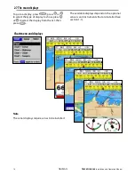
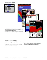
Page 14: ...select the type of display to show press or to select the display from the list then press 2 7 The main displays Chart menu and displays The available displays depend on the optional sensors and instr...

Page 15: ...SmartCraft system to be installed For information on using SmartCraft see the SmartCraft Gateway Installation and Operation Manual Note Press to go from a SmartCraft display back to your last chart o...

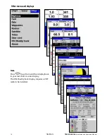
Page 16: ...Installation and Operation Manual 16 NAVMAN Other menu and displays Note Press to go from an Other display back to your last chart or sonar display The DSC Buddy track display requires a VHF radio to...

Page 17: ...of the displays called the active display has a yellow border and is controlled by the user Highway can not be the active display To change the active display press twice For example If Chart is the...

Page 18: ...ss also shows bearing to the destination BRG a black symbol In this example BRG is and COG is 4 To change the data displayed i Select Data setup ii Change a data field a Press the cursor keys to highl...

Page 19: ...ion 17 8 2 If the arrival radius alarm is enabled then an alarm will sound to show that the boat has reached the destination see section 17 8 A waypoint is a position that you can set on the TRACKFISH...

Page 20: ...display 1 Go to the routes display 2 Then follow step 3 as in starting a route from the chart display above Navigating The TRACKFISH navigates to each waypoint on the route in turn as described in se...

Page 21: ...ection 2 7 3 B Compass see section 2 7 4 C Chart scale see section 3 2 3 D Boat position see section 3 2 1 E Boat track see section 3 5 F Boat course and CDI lines see Appendix C CDI The boat is going...

Page 22: ...The Chart has two modes Centre on boat mode To switch to centre on boat mode in the chart display press The boat is at the centre of the chart As the boat moves through the water the chart automatical...

Page 23: ...leg as well as the total distance along the course The completed course can be converted into a route To use the distance and bearing calculator 1 Press until the chart display is displayed Press and...

Page 24: ...mall interval will give a shorter more detailed track and a long interval will give a longer less detailed track as shown in these examples Time intervals Interval Track 1 Track 2 3 4 or 5 1 sec 33 mi...

Page 25: ...t comes within the danger radius of a danger waypoint the unit can sound an alarm see section 17 8 A display option Controls how the waypoint is displayed on the chart see section 17 2 5 1 Waypoints d...

Page 26: ...aypoint from the chart display 1 In the chart display move the cursor to the waypoint to edit 2 When the waypoint data is displayed press 3 Change the waypoint data see section 5 2 7 Editing a waypoin...

Page 27: ...int See section 3 1 2 6 Navigation Routes A route is a list of waypoints that the boat can navigate along Routes can be created changed and deleted The TRACKFISH can have up to 25 routes Each route ca...

Page 28: ...ve the cursor to the end of the first leg and press v Repeat i to iv until the last waypoint in the route is placed and saved vi Press to complete the route Menu options while creating a route 1 To ad...

Page 29: ...1 In the routes display select the route to edit Press and select Edit on chart 2 The selected route is displayed on the chart with a circle around the first waypoint 3 Edit the route as described in...

Page 30: ...e received by the TRACKFISH s standard GPS antenna The accuracy of the corrected GPS position is typically better than 5 m 15 ft for 95 of the time WAAS covers all of the USA and most of Canada EGNOS...

Page 31: ...n Sonar functions require an optional sonar transducer to be installed and set up This section explains how to interpret the sonar displays when and why to use the different frequencies and how fish a...

Page 32: ...sh or object The area covered by the ultrasonic pulse is a rough cone shape and the echoes are strongest in the middle Clarity of water Particles or air in the water reduce the strength of the echo Co...

Page 33: ...C Hard bottoms such as rock or coral show as wide bands A C B Frequency and cone width Water Cone width Cone width Depth at 50 kHz at 200 kHz 25 20 5 50 40 10 100 80 20 150 130 30 200 170 40 300 250 6...

Page 34: ...bottom dwellers When to use 50 kHz The 50 kHz frequency is particularly suitable for use in deep water typically greater than 500 ft 150 m At 50 kHz the cone covers an area of water about four times...

Page 35: ...display filling in detailed echoes in the centre of the sonar cone When to use 50 200 kHz Operating the TRACKFISH at both 50 kHz and 200 kHz simultaneously on a split display can be very useful when...

Page 36: ...TRACKFISH 6500 Installation and Operation Manual 36 NAVMAN 50 kHz display 200 kHz display 200 50 Khz display Mixed display...

Page 37: ...ough the cone shaped ultrasonic pulse is displayed as a fish arch The 50 kHz frequency uses a wider cone than the 200 kHz frequency This makes the fish arches easier to see A fish arch starts when a f...

Page 38: ...et Auto mode 1 Go to a sonar display see section 9 2 Press select Range and select Auto Manual The TRACKFISH does not adjust the range automatically If the bottom depth is below the range the bottom w...

Page 39: ...hold is 50 then return echoes less than 50 of the maximum signal are ignored There is a separate threshold setting for each sonar frequency 50 kHz and 200 kHz The gain window To display or change the...

Page 40: ...us a bottom trace in a zoomed section see section 9 3 Split 50 200 Sonar histories at 50 and 200 kHz see section 9 4 Split A Scope Sonar history plus echo strength see section 9 5 9 Sonar fishfinding...

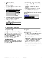
Page 41: ...r off 1 Press and select Bottom lock 2 Select On or Off or If Bottom lock is on pressing or will turn it off 9 3 Sonar Bottom display The display shows the sonar history on the right and the bottom si...

Page 42: ...ngest echo usually from the bottom D A vertical line showing the threshold the weakest echo to display on the sonar history E A vertical line showing the gain setting echoes above this strength will d...

Page 43: ...uches the gain line 7 Adjust threshold so that it is just to the right of the noise 8 Press to close the gain window 9 If required repeat these steps to adjust gain and threshold for the other frequen...

Page 44: ...ge Max RPM and Max fuel flow see section 17 11 Changing the Gauges display 1 Go to the Gauges display and press 2 To select the gauge type i Select Gauge type ii Select Analog round or Digital numbers...

Page 45: ...o the data display press select Other then select Data To select what data is displayed 1 Press and select Data setup 2 Change a data field i Press the cursor keys to highlight the field ii Press to d...

Page 46: ...ompletely fill the tank and follow procedure A about every tenth time you add fuel B When you part fill the tank 1 Before adding fuel go to the fuel display and write down the value of Remaining which...

Page 47: ...ing that both engines are under the same load Speed If the TRACKFISH has both GPS and paddlewheel speed available then you can select which to use The choice affects the calculated Range and Economy s...

Page 48: ...engine speed Wait for about 60 seconds for the boat to stabilise then press Wait while the TRACKFISH records the data 6 The TRACKFISH then asks you to set the throttle to achieve a target RPM For a tw...

Page 49: ...Fuel display press select Other then select Fuel 2 Press press and select the name of the curve to display on the fuel display Using a curve Compare your boat s performance now at the current RPMs wi...

Page 50: ...y The chart redraws with the tide station centred 4 Press and select Chart info 5 Select Tide height Choosing the date of the tide chart 1 Press 2 Select Today Next day or Prev day To choose a differe...

Page 51: ...CKFISH until loaded into the TRACKFISH with the LOAD command see below Saving data to the user card This saves all the TRACKFISH s waypoints all the TRACKFISH s routes or one of the TRACKFISH s tracks...

Page 52: ...error message saying that the card is not formatted Any data files on the card are deleted 1 Press and select Card 2 Select Format 3 Select Yes to confirm Warning Do not format a chart card Sorting t...

Page 53: ...waypoint at the boat position Distress waypoints have default names like DSTRSS01 The TRACKFISH displays a Distress warning Select OK to return to what you were doing Display to switch to Chart and d...

Page 54: ...A distress message creates a waypoint for the boat or you can create a waypoint at a polled boat s position To change the data of these waypoints 1 Press or to select a boat 2 Press and select Edit w...

Page 55: ...service quote the software version number and date 17 Setting up the TRACKFISH The TRACKFISH has a number of advanced features which are set up through the setup menu We recommend that you become fami...

Page 56: ...ors and instruments installed System see 17 1 Chart see 17 2 Sonar see 17 3 Favourites see 17 13 Time see 17 12 Alarms see 17 8 Units see 17 9 Comms see 17 10 Logs see 17 7 Track see 17 6 Fuel see 17...

Page 57: ...ction 2 3 To change only the chart palette see section 17 2 Key beep Enables or disables the beep when a key is pressed Auto power off See section 2 2 17 1 Setup System Factory reset This option retur...

Page 58: ...ible in sunlight Night Reversed colours for night to preserve night vision Map datum TRACKFISH GPS positions are based on a worldwide reference datum known as WGS 84 Most paper charts are based on WGS...

Page 59: ...h contours move on the TRACKFISH chart display to where they should be The positions of the boat waypoints tracks and lines of latitude and longitude on the TRACKFISH chart display remain unchanged Ap...

Page 60: ...ymetrics and Spot soundings Bath sndgs max The maximum depth for Bathymetrics and Spot soundings Tidal stream displays dynamic tide ows arrows on a chart showing the present tide stream and orientatio...

Page 61: ...values will display more fish symbols Digit size Use this to remove or change the size of the depth display on the sonar displays There is a choice of Small Medium and Large Palette Use this to select...

Page 62: ...e readings the TRACKFISH calculates these values by taking several measurements and averaging them A lower value averages measurements over a shorter period of time This gives the most accurate value...

Page 63: ...Connect the portable tank s to the engine through the fuel transducer s 3 Run the engine at normal cruising speed until at least 4 gallons 15 litres of fuel has been used per engine 4 Check the actua...

Page 64: ...chart 1 to 5 select a track number The selected track is shown on the chart Plotting Interval Select the plotting and recording interval The options are Distance or Time Distance Select the distance...

Page 65: ...l after an engine service or to count the engine hours between service intervals 17 8 Setup Alarms For the XTE Fish and Loss of DGPS fix alarms select to turn the alarm on or select to turn the alarm...

Page 66: ...2 sec depth is greater than the alarm trigger value Fish 1 short echo matches the pro le of a sh beep Temperature 1 2 sec temperature equals the alarm trigger value Temperature 1 2 sec rate of change...

Page 67: ...ompass T True north or M Magnetic north Temperature F Fahrenheit or C Celsius Wind optional Requires a wind instrument True or App Apparent Note that the units for wind speed are the speed units Press...

Page 68: ...ry settings should be sufficiently accurate for normal usage To calibrate the temperature readout first measure the water temperature with a thermometer known to be accurate Use the cursor keys to dis...

Page 69: ...set The difference between local time and UTC GMT Change local offset when daylight saving time starts and ends The range is 0 to 13 hours in 30 minute steps 17 12 Setup Time 1 Select Local offset 2 P...

Page 70: ...ptions required for Normal are Speed The simulated boat speed to use Course The simulated course over ground Note To select the start point go to the chart display before starting the simulation Then...

Page 71: ...f several instruments are connected For more information see the NavBus Installation Manual 18 2 Installation Options and Accessories and the documentation that comes with the antenna and any other un...

Page 72: ...at to sound alarms through the boat see section 18 4 GPS or DGPS antenna For GPS navigation see section 18 5 Sonar transducer For depth sounding and fish finding see section 18 6 Fuel sensors For fuel...

Page 73: ...from the compass at least 12 300 mm away from any radio transmitter and at least 4 ft 1 2 m away from any antenna Easy to read and operate If possible mount the display unit in front of the navigator...

Page 74: ...able to the black display unit connector turn the collar to lock the connector Black Black Power data cable Red Yellow Black 18 4 Installation Power data cable Main switch 12 24 V DC Fuse 2A The power...

Page 75: ...ble GPS or DGPS instrument or antenna connected by NavBus see section 18 11 or NMEA see section 18 12 In this case the TRACKFISH does not need its own antenna Note The TRACKFISH can apply the WAAS and...

Page 76: ...sensors Fit the optional diesel fuel kit following the instructions supplied with the kit Note SmartCraft engines have fuel flow sensors therefore Navman diesel sensors are not required as well For du...

Page 77: ...ge in all other instruments of the same type Each instrument can be assigned to a group of instruments If the backlight is changed in an instrument in group 1 2 3 or 4 then the backlight will automati...

Page 78: ...data cable Yellow GPS fuel Y cable White Setup and test 1 Put a blanking cap on any unused connector on the back of the display unit Ensure all connectors are plugged in and the display unit is in pla...

Page 79: ...lotter mode SONAR FISHFINDING Depth range 0 6 m 2 ft to 1000 m 3300 ft Sonar output Power Variable up to 600 W RMS Dual frequency 50 khz and 200 kHz Transom transducer cable length 10 m 33 ft Depth ac...

Page 80: ...an 1960 Indian 1975 Indonesian 1974 Ireland 1965 ISTS 061 Astro 1968 ISTS 073 Astro 1969 Johnston Island 1961 Kandawala Kerguelen Island 1949 Kertau 1948 Kusaie Astro 1951 L C 5 Astro 1961 Leigon Libe...

Page 81: ...corroded Test the fuse or replace it with a fuse known to be good Appendix B Troubleshooting This troubleshooting guide is written with the assumption that the user has read and understood the relevan...

Page 82: ...hanged when daylight saving time starts or ends 2 6Autopilot not responding to TRACKFISH no NMEA output a NMEA output disabled or the required NMEA sentences are not turned on Check NMEA settings see...

Page 83: ...b The transducer may have been damaged during launching running aground or while underway with debris etc If the transducer has been impacted it may have been kicked up on the bracket If it is not phy...

Page 84: ...ge see section 8 5 4 4 Bottom echo disappears or erratic digital reading while the boat is moving a Ensure the back of the bottom surface of the transducer is slightly lower than the front and the fro...

Page 85: ...ite based navigation tool see section 7 Leg The straight segments of a route between waypoints A route with four waypoints has three legs MOB Man overboard MOB function Starts navigating back to the p...

Page 86: ...d see section 17 8 an alarm will sound if the boat reaches a CDI line COG Course Over Ground Direction in which the boat is moving over the ground CTS Course To Steer Optimum course to steer to return...

Page 87: ...Corporation No 281 Hou An Road Chien Chen Dist Kaohsiung Taiwan R O C Ph 886 7 831 2688 Fax 886 7 831 5001 e mail seafirst seed net tw web www seafirst com tw Thailand Thong Electronics Thailand Co L...

Page 88: ...Made in New Zealand MN000388B Lon 174 44 535 E Lat 36 48 404 S NAVMAN TR AC K FISH 650 0...

Reviews: