Lone Worker Solution | Installation Manual
13
3.2.3
Input Wiring
1.
Push the 6-Wire Input Cable firmly onto the 6-Pin Input at the back of the Interface
Module. Check that the toggle on the white connector has latched into place.
2.
Connect Input Wire 1 at the other end of the 6-Wire Input Cable to the Qube’s I/O
cable, as follows:
Note – the colours shown below relate to a Qube 4 10-way connector
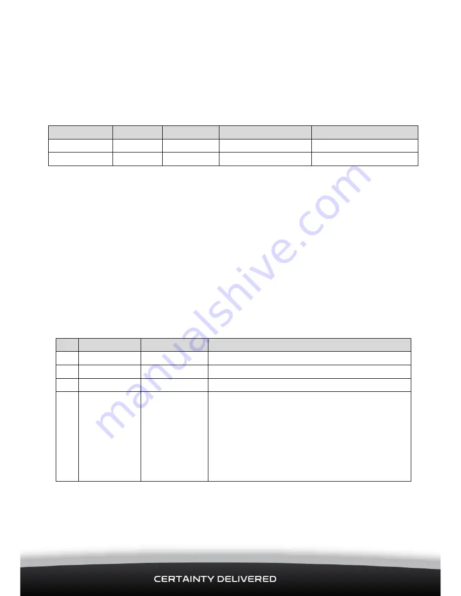
Input Wire
ConEx
Pin (Qube)
Wire Colour (Qube)
Function
1
DO-1
9
Light Green
Alert Acknowledgement
2 - 6
NOT USED
The Digital Output will pull to Ground and sink a maximum current of 250 mA when
activated.
The Digital Output has over-current trip protection and, if tripped, must be changed to OFF
or have a power cycle to reset the current trip.
3.3
Connect the Interface Module to the Ignition Loom or Fuse
Box
The Red wire on the Main Power Harness is supplied with a 2 Amp fuse.
Push the white connector on the end of the Main Power Harness into the power connector
on the front of the Interface Module. Check that the toggle on the white connector has
latched into place..
Connect ONLY the Black wire and the Red Wire to the vehicle ignition loom as follows:
Pin Wire Colour
Function
Description
1
Black
Negative/GND Vehicle Ground/chassis connection.
2
Yellow
OBDII
Not Used
3
Green
OBDII
Not Used
4
Red
+9/36 V DC
Main power connection (main vehicle supply)
on 12 / 24 V vehicles. The Main Power Harness
already has a 2 Amp fuse. The Red wire MUST
be connected to the SAME main power
connection as the Qube to enable the Lone
Worker Solution to operate while the vehicle is
parked with Ignition OFF. This includes isolated
vehicles and vehicles with an IPS.


