background image

FISH 4350 / 4380 

Installation and Operation Manual

24

NAVMAN 

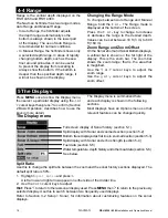
6-6 Cleaning and maintenance

Clean the screen 

only

 with a damp cloth and mild 

detergent when dirty or covered in sea salt. Avoid 
abrasive cleaners, petrol or other solvents.  
Cover or remove a transom-mounted 
transducer when repainting the hull. If painting 
over a through hull transducer with antifouling 
paint, use only one coat of paint. Remove the 
previous coat of antifouling paint by sanding it 
lightly.To optimize  performance, avoid walking 

on or jamming cables and connectors. Keep the 
transducer free of weed, paint and debris. Do not 
use a high pressure water blast on a speed sensor 
paddlewheel as it may damage the bearings.
When not in use, the FISH 4350 or FISH 4380 
can be removed from the installation bracket and 
stored in the Navman carry bag, or


left on the 

installation bracket and securely covered with 
the sun cover.

Depth range

•     

 2 ft (0.6 m) to 600 ft (180 m).

Display type

•     

TFT Colour.

•     

Screen resolution 320 high x 240 wide 

(pixels).

•     

LED multi-level backlighting.

Supply voltage

•     

10 to 16 V DC.

Supply current at 13.8 V

•     

300 mA min - no backlighting.

•     

400 mA max - full backlighting.

Output power


Variable, up to 200 W RMS.

Operating temperature

•     

32° to 122°F (0° to 50°C) 

Transom transducer cable length

•     

FISH 4350 33 ft (10 m).

•     

FISH 4380 26 ft (8 m).

Typical depth acquisition time from startup

•     

2 seconds at 100 ft (30 m).

Receiver sensitivity

•     

Better than 10 micro volts RMS.

•     

Dynamic range 4.0 million to 1 (120 dB).

Temperature measurement range

Appendix A - Speci

Þ

 cations

      New Zealand and Australia (C Tick)

     AS-NZS 3548.

·     Environment:  

IP67.

NMEA Output (FISH 4380 only)

NMEA 0183 (Ver 2.0) 4800 baud is a standard for 

interfacing marine electronic devices. The Navman 

Þ

 sh

Þ

 nder can output the following sentences:

•     

DBT (Depth Below Transducer)

•     

DPT (Depth and Keel offset)

•     

MTW (Water temperature)

•     

XDR (Battery voltage and fuel 

ß

 ow).

•     

VHW (Speed)

Fuel Computer (FISH 4380 only)

(optional fuel transducer(s) required)

•     Outboard carburetted two stroke and EFI 

petrol/gasoline engines: 30 to 300 hp.

•     Outboard four stroke petrol/gasoline 

engines: 90 to 300 hp.

•      Inboard petrol/gasoline engines: 50 to 300 hp.

•     Minimum 

ß

 ow rate: 1.3 U.S. gallons per 

hour (5 litres per hour).

•     Maximum 

ß

 ow rate:  34 U.S. gallons per 

hour (130 litres per hour).

FISH 4350 and FISH 4380

5.0" (126.0 mm)

3.5" (88.5 mm)

1.1" (27.9 mm)

5.7" (143.5 mm)

5.0" (126.0 mm)

FISH 4350: 89 mm (3.5")

1.2" (30.5 mm)

FISH 4380: 97 mm (3.8")

•     

32° to 99.9°F (0° 

to 37.7°C) 

      Resolution of 

0.1° unit.

Transducer 

frequency

•     

200 kHz.

Speed range

•     

1 to 50 kn (57.5 

mph, 96.6 kph).

Standards 

Compliance

•      

EMC:USA FCC 

Part 15 Class B.

       Europe 

(CE) 

EN50081-1 and 

EN50082-1

Summary of Contents for Fish 4350

Page 1: ...English 2 Espa ol 28 Portugu s 59 NAVMAN w w w n a v m a n c o m F I S H 4 3 5 0 4380 F I S H F I N D E R Installation and Operation Manual...

Page 2: ...ing practices NAVMAN NZ LIMITED DISCLAIMS ALL LIABILITY FOR ANY USE OF THIS PRODUCT IN A WAY THAT MAY CAUSE ACCIDENTS DAMAGE OR THAT MAY VIOLATE THE LAW Governing Language This statement any instructi...

Page 3: ...4 Using the FISH 4350 and FISH 4380 13 4 1 Interpreting the display 13 4 2 Fish detection and display 16 4 3 Gain 17 4 4 Range 18 5 The Displays 18 5 1 Sonar display 19 5 2 Sonar Zoom display 19 5 3 S...

Page 4: ...IMPORTANT NOTE ON USE While any sh nder can be used as an aid to navigation accuracy can be limited by many factors including the location of the transducer It is the user s responsibility to ensure...

Page 5: ...No transducer detected Enter simulate mode will appear Press or to select and press to accept If the transducer was not intentionally disconnected turn off the sh nder and refer to the section on Tro...

Page 6: ...e fishfinder generates data so that all the main displays appear to be operational Use Setup Simulate as follows 1 Press MENU twice to show the Setup menu 2 Highlight Simulate 3 Press to select On or...

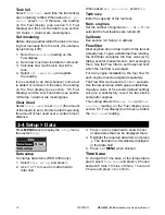
Page 7: ...the keys in more detail The Setup menu and options are summarized below The factory default settings are shown where applicable Each Setup menu option is explained in the following sections The Setup...

Page 8: ...to 2 hours The sh nder appears to turn off however all alarms operate normally To return to normal operation press any button Ideal to be used as an anchor alarm Factory reset This option returns all...

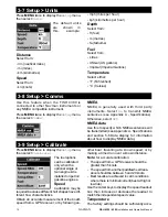
Page 9: ...n the palette represents a different echo strength as shown on the sonar displays There is a choice of ve colour palettes Black Blue White Vivid and 8 colour The rst four display more detail whilst th...

Page 10: ...see section 5 5 Fuel Display and the Low Fuel Alarm see section 3 6 Setup Alarms are meaningless Set remaining Before doing a partial re ll of the tank or remov ing fuel manually from the tank for ex...

Page 11: ...rms Press MENU twice to display the Setup menu then select Alarms Trigger settings can be de ned to suit the boat and individual preferences as follows Alarms can be set enabled to automatically detec...

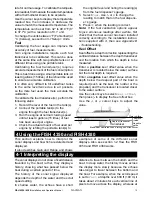
Page 12: ...s will be transmitted seeAppendixA Speci cations and section 5 6 Data display for information about how to display NMEA data Press MENU twice to display the Setup menu then select Calibrate The fuel o...

Page 13: ...eading to match that on the fuel dispens er s gauge 6 Press when the reading is correct Note If the fuel calibration options appear to give erroneous readings after a while rst check that the fuel sen...

Page 14: ...boat is anchored the echoes all come from the same area of bottom This produces a at bottom trace on the display The screen shot shows a typical sonar display with the Fish symbols turned Off covered...

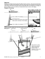
Page 15: ...for an example of the sonar display in such an environment A double bottom trace is shown on the display Sonar display of same area sh is visible on the display sh is hidden by the strong echoes off...

Page 16: ...e can form a barrier which the sh may not swim through In fresh water sh often collect around a thermocline Fish symbols The sh symbol can be customized or switched off altogether so that the echoes a...

Page 17: ...e sh passes out of the middle of the cone the reverse happens with a progressively weaker and deeper echo There are many reasons why sh arches may not be seen For example Poor transducer installation...

Page 18: ...a that is magni ed Use the or cursor keys to adjust the zoom range Use the or cursor keys to adjust the zoom offset 5 The Displays Press MENU once to show the Display menu then select a particular dis...

Page 19: ...n See section 4 4 Range for information about adjusting the Zoom Range and Zoom Offset Zoom bar Sonar history Zoom section Divider line 5 3 Sonar Bottom display To show the Sonar Bottom display highli...

Page 20: ...h species The user can de ne the level of the weakest and strongest echoes to be shown on the sonar Divider line between sonar history and A Scope Gain setting strongest echo for display Gainthreshold...

Page 21: ...y unit Power cable Mounting bracket screws included Warranty registration card This manual Sun cover for display unit Flush mounting kit Transom transducer includes cable kit and screws Transom Mount...

Page 22: ...ensure that the plugs left in the boat are not exposed to the elements Push the attached dust covers over the exposed ends of the plugs Keep the display unit in a dry clean place such as the optional...

Page 23: ...l transducer cable Wire the power cable for Auto power as described in this section to make sure the fuel counter starts as soon as the engine starts For twin engine installation a T connector needs t...

Page 24: ...rature 32 to 122 F 0 to 50 C Transom transducer cable length FISH 4350 33 ft 10 m FISH 4380 26 ft 8 m Typical depth acquisition time from startup 2 seconds at 100 ft 30 m Receiver sensitivity Better t...

Page 25: ...cuit see section 6 5 Wiring options f Check for corrosion on the power cable connector and clean or replace if required g Check fuses that are placed in line with the power cable A fuse can be blown d...

Page 26: ...but nothing is displayed The sh nder may be operating but the backlight settings may have been set too low See section 2 Basic Operation to adjust the sh nder backlight Press twice 8 The wrong langua...

Page 27: ...k that the value is not set to zero thentryincreasingthevalueuntilasteady ow rate is shown See section 3 3 Setup Fuel 13 There is no reading for fuel economy a The boat must be travelling through the...

Page 28: ...Singapore Malaysia Brunei Indonesia and Phillipines RIQ PTE Ltd Blk 3007 81 Ubi Road 1 02 440 Singapore 408701 Ph 65 6741 3723 Fax 65 6741 3746 e mail riq postone com Taiwan Sea rst International Corp...

Page 29: ......

Page 30: ...Lon 174 44 535 E Lat 36 48 404 S Made in New Zealand MN000240B NAVMAN FISH 4350 and FISH 4380...

Reviews:

Related manuals for Fish 4350