background image

NAVMAN 

8120/8084 

 Fuel, AIS, & Radar Addendum

11

separation or take into account viewing 
conditions.
1  Press 

MENU

 twice.

2  Select 

Radar

.

3  Select 

Overlay palette

.

4  Select your color preference.

Overlay Transparency

The transparency of the radar overlay can be 
adjusted, in case it obscures important chart 
features.
1  From the chart screen or pane, press 

MENU


once.

2  Select Radar overlay. If the box is 

unchecked, press 

ENTER

. A Radar menu 

option appears below.

3  Select 

Radar

.

4  Select 

Transparency

.

5  Adjust the slider to suit. Changes are seen 

on the chart in real time.

Also available on the 

Radar overlay


menu are shortcuts to enable/disable radar 
transmission (

Transmit

, see Manual, 

18-4) and to access the radar setup options 
(

Adjust radar

, see manual, 18-6).

Adjusting the quality of the radar window

Common problems that can degrade the 
quality of the radar window include:
•  sea clutter
•  rain clutter
•  false echoes (sometimes called ghost 

echoes) and background noise

•  side lobe patterns (false echoes that appear 

as an arc or a broken arc)

•  shadows (blind spots)
•  multiple echoes off the same object
•  incorrect threshold setting
If the radar is installed at a suitable height and 
in a suitable location on your boat, side lobe 
patterns and shadows (blind spots) caused 
by obstructions such as funnels or masts will 
be minimized. If you are having problems 
with these, you may need to relocate the 
scanner. Consult the Installation Guide for 
your NAVMAN scanner or talk to your dealer or 
installer.
Multiple echoes off the same object are 
most likely to occur when you are close to a 
large target and are usually only a temporary 
nuisance.
You can adjust the radar to reduce the effects 
of sea clutter, rain clutter, and interference 
from other radars. You can also change the 
gain mode setting and the gain level setting to 
help reduce false echoes.
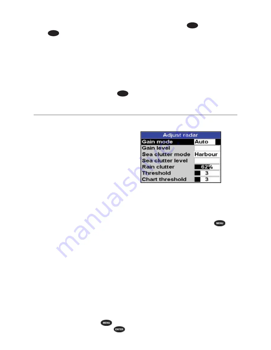
  From the radar window, press 

 then 

select 

Adjust Radar

 and press 

.

Changing the gain mode

Use the radar gain mode to specify whether 
you want to adjust the radar gain yourself or 
have it adjusted automatically. 
To change the radar gain mode:
1  From the radar window, press 

 then 

select 

Adjust Radar

.

2  Select 

Gain Mode

. There are three 

choices:
• 

Manual

. Adjust the radar gain yourself 

to suit your local conditions and 
preferences.

• 

Auto

. The radar gain is adjusted 

automatically.

• 

Range rider

. Select this to adjust the 

radar gain yourself for a particular radar 
range, then have these settings stored 
and automatically re-used whenever 
you operate at that range again.

Summary of Contents for 8084

Page 1: ...w w w n a v m a n c o m Fuel AIS Radar Addendum 06 07 Navman 8120 8084...

Page 2: ...190 mm 7 48 H x 285 mm 11 22 W x 76 8 mm 3 02 D Allow 3 mm clearance on each side for dust cover 8084 Display 213 4 mm 8 4 diagonal TFT color 800 x 600 pixels CPA Closest Point of Approach The closes...

Page 3: ...m s fuel level is shown on the fuel display tank levels as a red bar The alarm can also be set using the Alarms setup menu Boat speed sensors Selecting a boat speed sensor The fuel calculations can us...

Page 4: ...nots Gives a ground speed of 6 knots When the current is from ahead ground speed is less than water speed For this example If the boat travels for one hour uses 3 gallons of fuel per hour and has 50 g...

Page 5: ...ifficult to fill underfloor tanks to the same level twice due to air pockets so the more fuel used the more accurate the calibration To calibrate the sensor s 1 Record the level of the fuel in the tan...

Page 6: ...nnels This transmission may include information about the vessels MMSI number its call sign name position course heading speed rate of turn and type of vessel This unit can receive and display AIS inf...

Page 7: ...d on the chart by a red circle around the icon AIS Windows To go to the AIS windows press select More select AIS then press or to select one of the two windows Vessels or Safety msgs rx If there are m...

Page 8: ...ter by distance Vessels outside the radius selected from our current position are filtered off the chart Default value is set to 300 nm allowing all vessels to be displayed on the chart within that di...

Page 9: ...play called the PPI Plan Position Indicator Typically your boat is in the centre of the radar window with concentric range rings surrounding it The range rings help you to quickly estimate the distanc...

Page 10: ...plete the radar enters standby mode and is ready to transmit Selecting standby mode or transmit mode You can quickly change between these two modes 1 From the radar window press and set the Transmit o...

Page 11: ...suitable height and in a suitable location on your boat side lobe patterns and shadows blind spots caused by obstructions such as funnels or masts will be minimized If you are having problems with the...

Page 12: ...an offshore environment Changing the sea clutter level If the sea clutter level is set too low a lot of sea clutter will be displayed If the sea clutter level is set too high small targets may not be...

Page 13: ...rails setting From the radar window press then set the Target trails option to target trails are on or target trails are off Using the VRM EBL Use one or both of the VRM EBL Variable Range Markers Ele...

Page 14: ...ting VRM Use this to measure the range and bearing between two locations on the radar window such as a headland and a buoy 1 From the radar window press then select VRM EBL 2 Select VRM EBL then 1 VRM...

Page 15: ...ed so that the radar window is offset from the centre to give you the maximum view ahead Set Offset the PPI centre in the radar window This works only when you are using relative motion RM mode Use th...

Page 16: ...larm The size of target is shown as a percentage 100 is maximum sensitivity meaning that very small targets will trigger the guard zone alarm 0 is minimum sensitivity meaning that only very large targ...

Page 17: ...your radar it can cause interference patterns on the radar window Interference patterns always appear in a different place with each sweep They can be randomly scattered bright dots or dotted lines th...

Page 18: ...e is aligned with the displayed chart and the compass An accurate bearing alignment is particularly important when the radar image is overlaid onto the chart Adjust this on a chart window with the rad...

Page 19: ...the edge of the radar window often producing a spiral effect Generally the stronger the interference the wider the interference lines a Use the interference rejection feature to reduce interference pa...

Page 20: ...NAVMAN 8120 Physical Dimensions NAVMAN 8084...

Page 21: ...Lon 174 44 535 E Lat 36 48 404 S Made in New Zealand MN000753B G Navman 8120 8084 Fuel AIS Radar Addendum...

Reviews: