9
EN
TECHNICAL DATA
•
Voltage 8 – 30V direct or alternating
•
Use: maximum 150mA
•
Number of codes: 100, of which 1 is an administrator code
•
Length of code: optional, from 4 to 16 characters
•
2 separate relay exits
•
256-bit encrypted connection to the relay unit
•
Capacitive illuminated keys
•
Installation into a door wing
INDEX
1. DEVICE COMPONENTS ......................................................... 9
2. DESCRIPTION AND CORRECT USE OF KEYPAD ............ 9
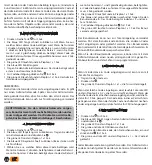
3. ENTERING THE ADMINISTRATOR CODE .......................... 10
4. ENTERING THE USER CODE ................................................. 10
5. UNLOCKING THE DOORS ...................................................... 10
6. DELETING THE USER CODE .................................................. 10
7. CHANGING THE ADMINISTRATOR CODE ...................... 10
8. DELETING THE ENTIRE BASE ............................................... 11
9. RESTORING FACTORY SETTINGS (RESET) ...................... 11
10. DISABLING THE ILLUMINATION OF THE KEYPAD ........ 11
11. MAINTENANCE AND CLEANING OF THE DEVICE ........ 11
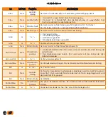
12. TABLE OF SIGNALS ................................................................. 12
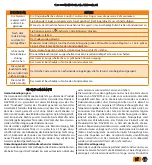
13. ERROR DESCRIPTION AND ELIMINATION ...................... 13
14. MANUFACTURER’S WARRANTY ........................................ 13
QUICKGUIDE ............................................................................ 53
2. DESCRIPTION AND CORRECT USE OF KEYPAD
The keypad has 10 digits and two function keys: (the plus),
which is used for adding, and (the checkmark), which is used
for code deleting and confirming or for unlocking. The keypad is
illuminated with blue backlight. The function keys are illuminat-
ed with green backlight when a correct code has been inserted
or when a suitable function is being activated. Red backlight is
activated when the code is incorrect or when a suitable func-
tion is activated. Under strong light the illumination of the key-
pad is poorly visible and the keys will appear white. Should the
programming of the keypad be made under strong light, it is
recommended that you shade the keypad in order to better see
the illumination and the light signals. When any of the keys is
being pressed, you will hear a short beep, which signals that the
key has been activated.
The keys are capacitive, and each has a sensor underneath,
which detects a finger that has been pressed over. In order to
activate a key, you have to cover the entire digit with your fin-
ger, by touching it lightly and quickly. If the finger approaches
the key slowly, it might not activate the key.
100 different codes can be stored in the keypad. Each code
can be of arbitrary length: at least 4 digits and not more than
16 digits. The first code that is set is the administrator’s code.
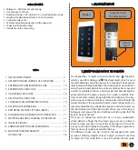
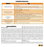
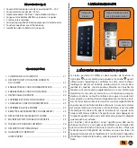
1. DEVICE COMPONENTS
Factory
reset
Relay unit with
the reset button:
Keypad:


