rev. 05 of 15-01-20 / pag. 2
2
___________________________________________________________________________________________
Ensure compliance with standards in force for electrical wiring.
The devices must be connected to the mains and remain permanently powered.
Omnipolar disconnection must be included in the mains.
The installation of a detector must not be a substitute for the correct installation, use and maintenance of
combustible gas appliances and equipment and for ventilation and exhaust systems for fumes.
Carefully read the instructions and electrical wiring diagrams in this document and follow them to the letter.
Keep this document in a safe place for future consultation.
The device must be installed by qualified technicians.
Installation
Since carbon monoxide weighs the same as air, it will be concentrated near the same height as the appliance
that manifests combustion defects or that is located in premises with insufficient ventilation.
Install about 2 metres (minimum 1 metre, maximum 3 metres) from the gas-operated appliance and at standard
face height of the occupants in those premises; example: 130…170cm in a kitchen, 50...100cm in a bedroom.
The detector
must not
be installed:
•
outdoors
•
too close to stoves, cooking appliances and, more in general, to gas appliances
•
near sinks and taps
•
near exhaust hoods, windows, fans, or ventilation apertures.
•
in areas where dirt and/or dust can clog the front grille of the detector
•
where the temperature or humidity exceeds the detector's operating limits
•
in closed spaces (behind curtains, inside cupboards etc.).
Commissioning
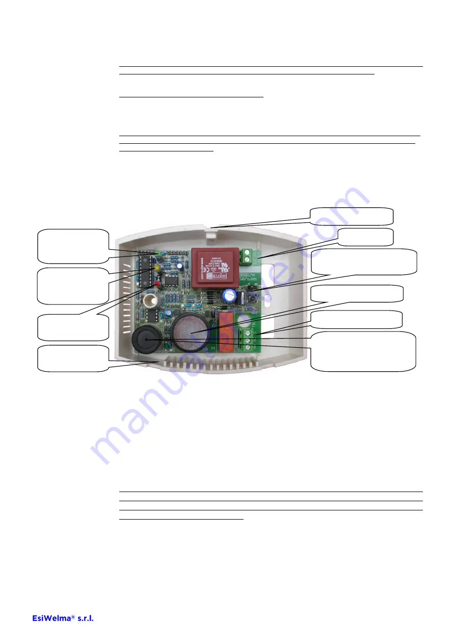
Select the relay operational mode by positioning jumper E1
E1 positioned towards A = continuous relay control
E1 positioned towards B = pulsed relay control (0.5s ON every 10s)
Power up the detector and make sure the initial operational test, the display of the firmware version and the
sensor warm-up is executed as indicated on the operational table.
At the end of the warm-phase, the detector enters normal operation mode by pressing button S1 for at least 1
second; check that the alarms act in conformity to what is indicated in the operational table and that the solenoid
valve or other command and/or alarm device connected to the relay are correctly engaged.
It is advisable to repeat the operational test at least once a year, or after a prolonged period of stoppage.
If other test methods are used instead of the one described, the detector may generate different, unexpected
responses. In particular, the use of inappropriate substances or vapours (alcohol or silicon-based solvents etc.)
or in any case, high concentrations of test gases could cause permanent damage to the sensing element and
may cause the detector to operate incorrectly.
After the wiring is completed and the operational checks have been made, power down the detector, and tilt the
front cover slightly downwards to fasten it onto the two clip-on points shown in the figure.
Rotate the cover upwards, making sure that all three LEDs are centred.
Press down firmly on the top of the cover and tighten the locking screw.
Power up the detector and make sure the initial operational test, the display of the firmware version, the sensor
warm-up and the passage to normal operation is executed correctly.
___________________________________________________________________________________________
Installation and
Commissioning
Power supply
Configuration jumper E1 and
test button S1
8A / 250Vac relay output
Piezoelectric buzzer
Green LED
Power supply /
Warm-up
Yellow LED
Sensor Fail / Gen-
eral Abnormality
Red LED
Alarm
Electrochemical cell sensor
(duration 6 years from date of
manufacture)
Cover
clip-on point
Cover locking screws


