


16 About the Boiler
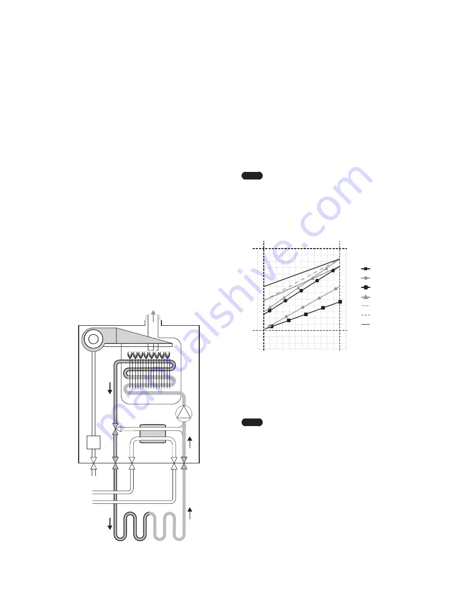
2.6.2 Operating According to Outdoor
Temperature Conditions
The
O
utdoor Reset Control feature
m
ay be used to enhance
energy efficiency while
m
aintaining opti
m
al heating
perfor
m
ance. With the
O
utdoor Reset Control, the space heating
te
m
perature setting auto
m
atically changes according to the
outdoor te
m
perature and the current space heating syste
m
application (syste
m
load).
You can configure the
O
utdoor Reset Control settings on the
front panel by entering the Special Para
m
eter Setting
m
ode.
Refer to “10.5 Setting the Para
m
eters” on page 43.
Note
The
O
utdoor Reset Control feature re
q
uires
installation of an outdoor te
m
perature sensor, and it
only works when the boiler is running in the nor
m
al
operation
m
ode.
I
t does not work when the boiler is
running in either the
M
ini
m
u
m
(
MI
N) or
M
axi
m
u
m
(
M
AX)
m
ode, or when the boiler’s front panel displays
a fault.
45 40 35 30 25 20 15 10 5 0 -5 -10 -15 -20 -25
185
194
176
167
158
149
140
131
122
113
104
95
86
77
68
59
50
113 104 95 86 77 68 59 50 41 32 23 14 5 -4 -13
°F
°C
85
90
80
75
70
65
60
55
50
45
40
35
30
25
20
15
10
°F °C
Absolute
M
AX
Absolute
MI
N
O
utdoor
High
MI
N
O
utdoor
Low
MI
N
High
M
ass Radiant
Low
M
ass Radiant
Cast
I
ron Baseboard
Custo
m
Radiator
Finned Tube Baseboard
Fan Coil
Space Heating Te
m
perature Setting for the
O
utdoor Reset Control Feature
The following tables list the default space heating te
m
perature
range by syste
m
heat load and the applicable outdoor
te
m
perature ranges.
Note
To connect the outdoor te
m
perature sensor to the
boiler, carefully follow the connection instructions
provided in the “12.5
O
utdoor Te
m
perature Sensor
(
O
ptional)” on page 66.
2.6 Operating Modes
2.6.1 Operating in Space Heating Mode
To operate the Space heating
m
ode, press the Space heating
button on the front panel and select a heating te
m
perature
setpoint higher than current heating te
m
perature.
1. When the boiler detects a re
q
uest for heating production
(fro
m
the installation’s roo
m
ther
m
ostat, for exa
m
ple), the
3-way valve goes to heating position and the circulating
pu
m
p starts up.
2.
I
f the boiler water te
m
perature is lower than the desired
te
m
perature setpoint, the boiler ignites and heats up the
heating installation until the selected boiler te
m
perature
is reached. The boiler’s electronic control
m
odulates
the burner output to adapt to the installation’s heat
re
q
uire
m
ents at all ti
m
es and so that the installation’s water
te
m
perature re
m
ains constant. This prevents the installation
fro
m
overheating and reduces heat loss as
m
uch as possible.
3. When there is no further heating de
m
and (e.g. when
the desired a
m
bient te
m
perature selected on the roo
m
ther
m
ostat is reached), the burner is extinguished (if it was
ignited) and the circulation pu
m
p continues to run during
the post-circulation ti
m
e (
m
ini
m
u
m
3
m
inutes), to protect
the boiler fro
m
overheating due to ther
m
al inertia in the
installation.
Air
I
n
Air
I
n
Exhaust
Gas
Blow Fan
I
gnitor
Gas
Valve
Gas
I
nlet
Flow
O
ut
CH
Return
Three
-way
Valve
DHW Heat
Exchanger
Circulation
Pu
m
p
Heat
Exchanger
Summary of Contents for NCB-24LDWE
Page 65: ...Appendices 65 12 4 Ladder Diagram 3 15A...
Page 69: ...Memo...
Page 70: ...Memo...
Page 71: ...Memo...


