59
2.4.3.2 Wiring Diagram - External LWCO
T/S_ZONE3
W
C
T/S_ZONE2
R
W
C
T/S_ZONE1
R
W
C
AC24VN
AC24VL
lLWCO
R
W
C
T/S_Recir
COM
NO
NC
ZONE_V/V3
COM
NO
NC
ZONE_V/V2
COM
NO
NC
ZONE_V/V1
Neutral
Line
Line
LWCO
LWCO
Note
The boiler supplies 24 VAC at the LWCO power terminals
(CNC3).
For terminal type LWCO appliances, a typical wiring method is
shown below (same voltage for control and burner circuit):
LWCO
Terminals
Neutral
Jumper
Line
LWCO
To Boiler LWCO Terminals
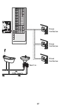
Summary of Contents for NaviCirc
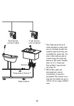
Page 41: ...41 Return Water NaviCirc Temperature Sensor Wired Push Button Wired Push Button...
Page 90: ...MEMO...
Page 91: ...MEMO...

