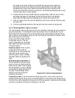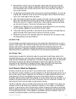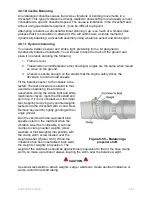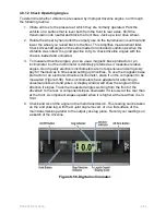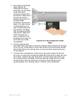
Figure 8-43 - Exploded view of a heavy-duty truck driveshaft.
4.1.0 Driveline Geometry
Two types of driveline configurations are used to transmit drive torque to the drive
wheels: the parallel-joint driveline and the non-parallel or broken-back driveline. In the
parallel-joint type, all the companion flanges or yokes in the driveline are on a parallel
plane to each other with working angles of the joints of a given shaft being equal and
opposite (
Figure 8-44
). For instance, if the transmission output shaft centerline angles
down 5 degrees from a true horizontal plane, the centerline at the front of the auxiliary
main shaft or rear axle pinion shaft must angle 5 degrees up.
Figure 8-44 - Parallel joint driveline arrangement.
With the no-parallel or broken-back installation, the working angles of the U-joints of the
driveshaft are equal, but the companion flanges and/or yokes are not parallel (
Figure 8-
45
). For example, the transmission yoke is angled 3 degrees down from horizontal
plane, while the rear axle pinion flange is angled up at 12 degrees. Providing that the U-
joint angles of this propeller shaft remain equal, the shaft will run vibration free.
NAVEDTRA 14050A
8-50


