background image


Important Safety Instructions 

Please read this owner’s guide carefully and save it for future reference. 
Important safety instructions 

1.


Read these instructions 

2.


Keep these instructions 

3.


Heed all warnings 

4.


Follow all instructions 

5.


Do not use this system in dangerous area 

6.


Install in accordance with the manufacturer’s instructions 

7.


Do not install near any heat sources, such as radiators, heat registers, stove or 
other apparatus that produce heat 

8.


Only use attachments/accessories specified by the manufacturer 

9.


Unplug and take out the battery when it is unused for long periods of time 

10.


Refer all servicing to qualified service personnel. Servicing is required when the 
system has been damaged in any ways 

 
WARNING: 

1.


Do not place naked flame sources, such as lighted candles, on or near the 
product 

2.


Do not subject batteries to mechanical shock 

3.


In the event of a battery leaking, do not allow the liquid to come in contact with 
the skin or eyes. If contact has been made, wash the affected area with copious 
amounts of water and seek medical advice 

4.


Do not use any chargers other than the ones specifically provided for the 
equipment by the manufacturer 

5.


Do not leave a battery on prolonged charge when not in use 

6.


After extended periods of storage, it may be necessary to charge and discharge 
the batteries several times to obtain maximum performance 

7.


Batteries works in temperatures between 23°F(-5°C) to 113°F (45°C)   


CAUTION

: Do not make unauthorized alterations to the product; doing so may compromise 

safety, regulatory compliance, system performance, and may void the warranty. 

WARNING

: Contains small parts which may be a choking hazard. Not suitable for 

children under age 3. 

WARNING

: This product contains magnetic material. Contact your physician if you 

have questions on whether this might affect the operation of your implantable 
medical device. 

NOTE:


Product markings are located on the bottom and inside battery chamber of the product. 
This product contains no user serviceable parts. Contact Navatics Customer Service for all 
servicing concerns. 


Summary of Contents for Mito

Page 1: ...I Underwater Drone Owner s Guide...

Page 2: ...ontact with the skin or eyes If contact has been made wash the affected area with copious amounts of water and seek medical advice 4 Do not use any chargers other than the ones specifically provided f...

Page 3: ...aft EN 301 489 1 V2 2 0 2017 03 Draft EN 301 489 3 V2 1 1 EN 300 440 V2 1 1 2017 03 EN 62479 2010 EN 60950 1 2006 A11 2009 A1 2010 A12 2011 A2 2013 FCC Rules and Regulations Part 15 Subpart B Class B...

Page 4: ...terference will not occur in a particular installation If this equipment does cause harmful interference to radio or television reception which can be determined by turning the equipment off and on th...

Page 5: ...luating Conditions and Safety 14 Power On and Connect 16 Sensor Calibration 19 Preparing for Launch 20 Diving 21 After Diving Cleaning 22 Manage Dive Log 22 View Image 22 Download Image 23 Care and Ma...

Page 6: ...t lock from 45 to 45 enables it to capture a stunning shot while moving forward or backward Control wirelessly up to 500M The custom designed remote controls Navatics MITO uses radio frequency It conn...

Page 7: ...mote controller Smart device mount A B OTG Micro USB Type C Lightning cables Smart battery Smart battery charger Buoy and remote charger 2x Type C charging cable USB Data Cable Transport foam box May...

Page 8: ...rmal Blue Calibrating Red Problem occurred See trouble shooting on page 24 1000 lumen LED Light x 2 Right thruster Lens protector connector 4K Camera Left thruster NOTE Use it on land to protect the l...

Page 9: ...t extra flotation NOTE With extra weight MITO might not be able to keep positive buoyancy It means MITO might sink instead of float when the motor is off WARNING DO NOT mount any dangerous object on t...

Page 10: ...battery Charger for battery 1 Plug the power cord into the connector on the smart battery 2 Connect the charger with the charging cord 3 Plug in to power socket 4 Check the power indicator for chargi...

Page 11: ...the remote to the regular charging port on USB charger White port 3 Plug the USB charger into power socket 4 Check power indicator for charging status NOTE Charge the wireless communication buoy with...

Page 12: ...Android switch Right touch pad Left touch pad Pitch lock stick Light indicator Charging port Power Switch Y Motor switch X Flatten out B LED light switch Smart device connection port Smart device moun...

Page 13: ...icro USB and Type C OTG Cables and a lightning cable are provided Please choose according to your smart device port type NOTE Please make sure your Android device support OTG connection For some devic...

Page 14: ...oftware firmware update tools and plans for improvements and new features Download The Navatics App can be downloaded at Navatics official website www navatics com NOTE Keep your App up to date Make s...

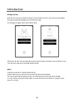
Page 15: ...APP will automatically connect to the remote controller once connected users can start streaming and controlling Navatics MITO NOTE Internet connection is needed when binding Please make sure you turn...

Page 16: ...e used by that account The app will try to automatically connect to the latest connected device Parameters setting Camera parameters setting Photo video button Photo video switch The media file Light...

Page 17: ...12 Quick Start...
Page 18: ...he wireless communication buoy connect it to MITO and check both of their light indicators 3 Turn on the remote controller and select the right mode 4 Connect the smart device and open Navatics App NO...

Page 19: ...owded areas including but not limited to beaches diving sites operating fields etc Attention In areas with lots of electromagnetic interference you may experience lag or artefacts in the video stream...

Page 20: ...light Do NOT touch the propellers when powered Do NOT dive when current speed is greater than 1 2m s Do NOT put wireless communication buoy into water when wave is higher 0 5m Do NOT use MITO when vis...

Page 21: ...When started MITO is going to check for the states of its sensor In the process it will turn on the LED lights as an indicator as well as changing the color of LED ring to indicate the process Once al...

Page 22: ...t the tether roller is ready to transmit video and data to the remote controller 3 Hook the tether on the tether hook NOTE It is strongly recommended to cover the Type C charging port with the provide...

Page 23: ...port on top of the remote controller Android base devices require OTG cable Micro USB and Type C OTG cable provided iOS base devices can be connected with common lightning cable provided 4 Once the us...

Page 24: ...play Race to MITO 2 Start the Navatics app in the smartphone 3 Go to Camera View and click on the parameters settings icon to open the dialog box 4 Go to the calibration page in the app 5 Place MITO o...

Page 25: ...75 charged before you go diving When the battery in the drone reaches 25 when diving go back to shore Using tether To avoid tangle on the tether do not unroll it all at once Unroll it 3 feet 1 meter...

Page 26: ...art MITO Once the drone is in water turn on the motors of the drone by pressing the Y button on the remote controller Press again to turn off the motor and the drone will automatically float to the su...

Page 27: ...enough and stop recording when MITO is floating on the surface and the thrusters are turned off or when it is running out of battery The dive log will record various data including duration of dive m...

Page 28: ...Download Image To transfer full size videos and images to your devices you need to use the USB data cable provided to connect MITO directly to your device NOTE Please turn off MITO before downloading...

Page 29: ...buoy will blink Binding the communication buoy and remote to your account Check your internet connection Check if you are logged in to your account The binding should be done in sequence i e the remo...

Page 30: ...3 Make sure that you are picking the right propeller R or L 4 Once installed screw the new propellers back in place NOTE Use 1 16inch 2mm hex key screwdriver to remove screws The R propeller can only...

Page 31: ...cing them back in 4 Once finished reinstall the rotor and fix them with the lock nut 5 Reinstall the thruster s rear cover NOTE Use 1 16inch 2mm hex key screwdriver to remove screws Updating Firmware...

Page 32: ...ime 4 hours Normal Use 2 hours Intensive Use High Speed Charging time 1 5 hours Weight 850g Operating Temperature Range 20 C to 60 C Charging Temperature Range 10 C to 60 C Input Voltage 16 8V 5A Safe...

Page 33: ...ng Time 2 5 hours Fast Charging 5 hours Normal Charging Battery Capacity 38 8Wh 3 7V 10500mAh Waterproofing 1m IP68 Weight 1 7 kg 3 75 lbs Dimension 330 mm x 250 mm x 55 mm Tether Strength 100 kg Kevl...

Page 34: ...prevent sand built up 14 Mobility Capable of moving in 4 axis forward backward rotate left rotate right up down and tilt up tilt down 15 Attitude and Depth Control Constantly maintain depth heading a...

Page 35: ...1 Learn more at www navatics com...

Reviews: