background image

BHM 

01/27/20 

NTV-DOC350 

Agreement

End user agrees to use this product in compliance with all State and Federal laws. NAV-TV Corp. would not be held liable for misuse of its product.  

If you do not agree, please discontinue use immediately and return product to place of purchase. This product is intended for off-road use and passenger 

entertainment only.  

3 | 

P a g e


Smart-Link Installation 


Smart-Link was designed to be as flexible as possible (for 12v systems) and is adaptable for use with two 
different screen (input) types.  Below are all Input, Output & system control options available.  All functions 
are simultaneously available. 

General INPUT (& controlling options): 


1.


4-wire resistive touch panel ribbon input (OS has built-in calibration programming) 

2.


Factory touch screen via UART (HDMI connection) 

 vehicle specific, must be combined with an 

additional NAV-TV module for best functionality (see chart pg 2) 

NOTE: if touch does not function over 

HDMI cable, you must use the provided TOUCH (ribbon cable) connection to the interface (provided 
with interface kit).


3.


Controller knob (custom fabrication recommended for best result)  

4.


Microphone (for BT phone calls & controlling SmartPhone via specific voice commands) 

5.


Camera input (only used in a universal application 

 ie, no source unit switching is available) 

General OUTPUT (AV output): 

1.


Low resolution composite video (yellow RCA) 

2.


High definition Digi-RGB (HDMI connection 

 connects to proprietary NAV-TV module, see chart pg 2) 

3.


Low-Level Audio stereo output (red & white RCAs) 

 global audio output 

 connects to AUX input 

(NOTE: Installer is  


Power Connections: 

1.


Black wire: connect to ground (-) 

2.


Yellow wire: connect to constant 12v (+) 

3.


Red wire: connect to ACC 12v (+) 

Other required connections: 
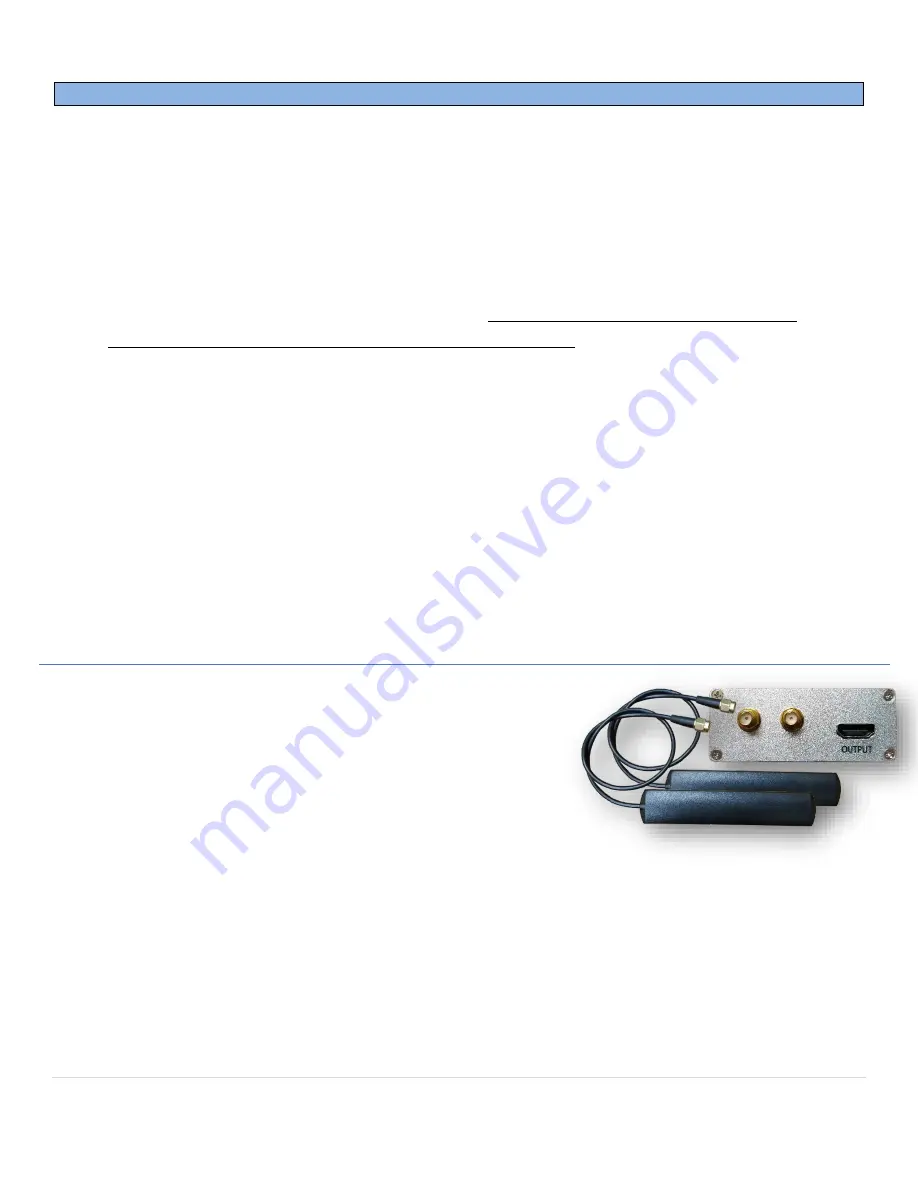
1.


Once you have good secure placement for the Smart-Link device, connect the provided BT and WIFI 
antennas to the ports on the side of the unit and try to stick the antenna side as close to the passenger 
compartment as possible, preferably with no metal is blocking the antenna (from smartphone). NOTE: 
these antennas are the same and therefore can be connected to either port. 


2.


Audio output should be determined by the installer 

 the Smart-Link unit provides global low-level 

audio output via Red & White RCAs, connect to an existing vehicle AUX input (may require adapter). 

NOTE: if no AUX input is available, contact NAV-TV for options. 


3.


Follow one of the connection guides on pages 4-6 choosing input & output type for control and video.  

Summary of Contents for NTV-KIT956

Page 1: ...5 9770 FAX 561 955 9760 www nav tv com info nav tv com Overview The Smart Link is a smartphone interface that adds convenience features to any screen or specific NAV TV interface kits equipped with Digital RGB input This module has composite and proprietary HD video output and can be controlled by either a 4 wire resistive touch screen not provided optional knob controller or OEM touchscreen if av...

Page 2: ...M 3 5mm NTV KIT780 GM LVDS CHEVY GMC CADDY OEM touch OEM 3 5mm NTV KIT796 GM GVIF Chevy GMC Caddy OEM touch OEM 3 5mm NTV KIT798 IOB RVC CHEVY GMC 7 OEM touch OEM 3 5mm NTV KIT837 BMW EVO ID6 BMW OEM touch USB AUX adapter NTV MOD031 Bentley MOD Bentley OEM touch OEM 3 5mm NTV KIT837 BMW EVO ID6 BMW OEM touch OEM 3 5mm NTV KIT850 PCM41 CAM Porsche OEM touch OEM 3 5mm NTV KIT880 JLR 17 Jaguar Land R...

Page 3: ...rophone for BT phone calls controlling SmartPhone via specific voice commands 5 Camera input only used in a universal application ie no source unit switching is available General OUTPUT AV output 1 Low resolution composite video yellow RCA 2 High definition Digi RGB HDMI connection connects to proprietary NAV TV module see chart pg 2 3 Low Level Audio stereo output red white RCAs global audio outp...

Page 4: ...tate and Federal laws NAV TV Corp would not be held liable for misuse of its product If you do not agree please discontinue use immediately and return product to place of purchase This product is intended for off road use and passenger entertainment only 4 P a g e Smart Link diagram Global Usage ...

Page 5: ... and Federal laws NAV TV Corp would not be held liable for misuse of its product If you do not agree please discontinue use immediately and return product to place of purchase This product is intended for off road use and passenger entertainment only 5 P a g e Smart Link diagram touchscreen overlay ...

Page 6: ...te and Federal laws NAV TV Corp would not be held liable for misuse of its product If you do not agree please discontinue use immediately and return product to place of purchase This product is intended for off road use and passenger entertainment only 6 P a g e Smart Link diagram knob controller ...

Page 7: ...Smart Link To begin follow the instructions on the compatible NAV TV interface for proper installation Connect the provided HDMI cable from the OUTPUT port on the Smart Link to the DIGITAL RGB IN or LVDS IN port HDMI on the interface Follow the steps below to set up the Interface for Smart Link connection a With the system on put dip switch 1 in the DOWN position b Activate the NAV INPUT by pressi...

Page 8: ...en FACTORY MODE The passcode is 0000 then press OK Inside FACTORY MODE there are options for control like touchscreen calibration or boot logo NOTE alternatively you may calibrate the touchscreen by exiting to the main OS or disconnect any phone connected press and HOLD the touchscreen for 15 seconds and calibration crosshairs will appear Inside FACTORY SETTING there are options for advanced contr...

Reviews: