


https://www.naturewater.eu
Item 63922, 63923
Page 15
11 2023-1
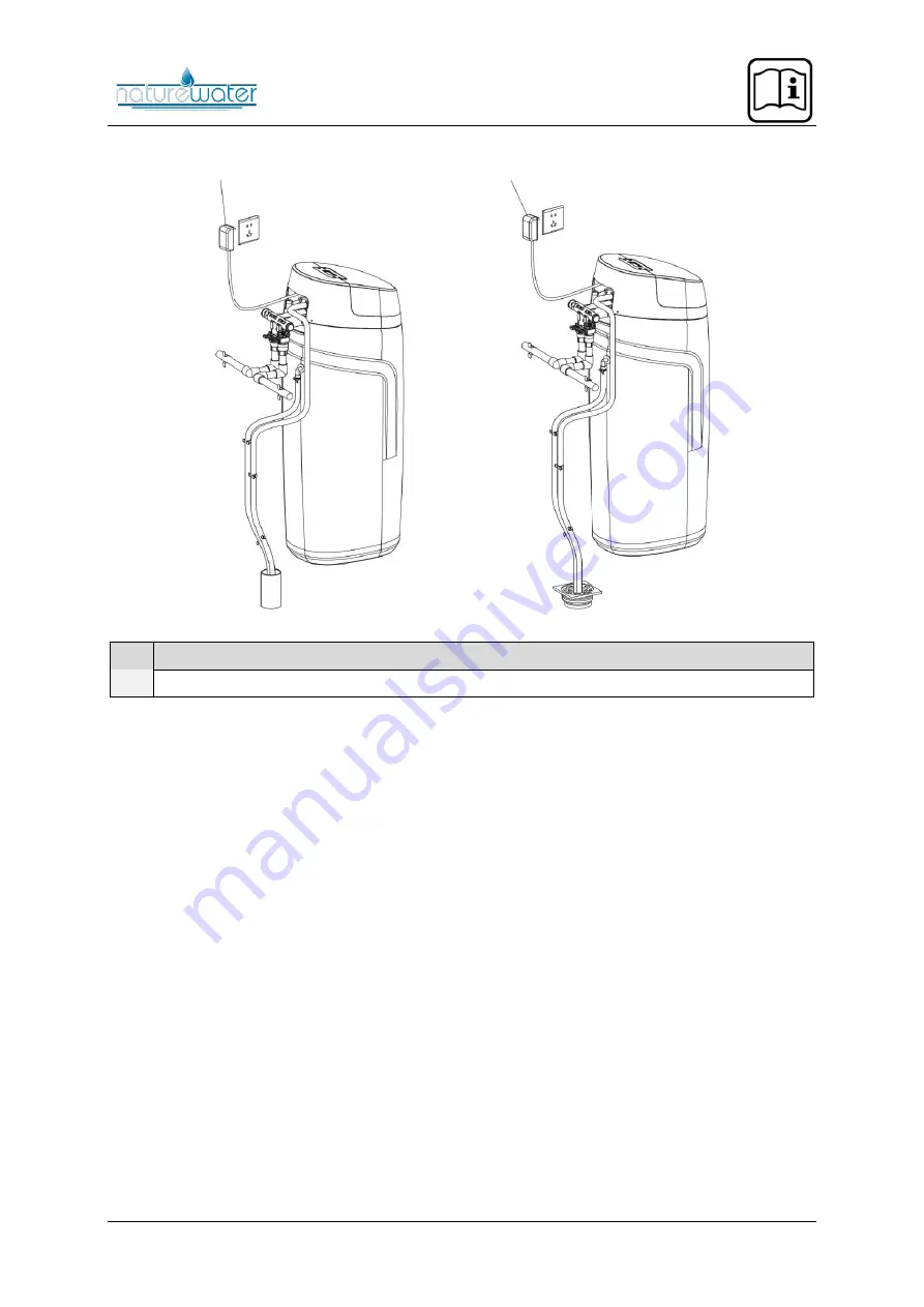
Fig.
5
Fig.
6
№
Name
1
Transformer
If an operating room is available, it is recommended to use the installation method shown in Figure 5.
Otherwise, only the drain pipe and the overflow pipe can be inserted into the floor drain. As shown in
Figure 6, make sure that the two pipes are fixed to the wall to prevent the pipe from being flushed out
of the floor drain when emptying. This can have detrimental effects and lead to damage.
Install connections
•
The connection and laying of the pipe system is carried out in accordance with the provisions
of the construction standards for water supply and drainage pipes. The inlet and outlet interfaces
of the water softener and the water pipe interfaces are connected by a ¾″ PPR inner pipe or a
corrugated pipe and must be installed on the same axis (see installation plan). The inlet and
outlet points must not be installed in reverse.
•
Connect the water inlet and outlet pipes, the drain pipes, and the overflow pipes in sequence to
ensure that all connections are tight and that there are no leaks. It is recommended to use
flexible pipes to connect the water softener inlets and outlets, the drain, and the overflow (note:
304 stainless steel, alloy forged steel, high-strength engineering plastics, and other materials
are to be used for the connection of pipe fittings and valves; valves and pipe fittings made of
iron are strictly prohibited).
Installing the drain and overflow pipes
•
First loosen the clamp and insert it into the prepared pipe, then insert the pipe into the drain and
overflow connection to the floor, and finally turn the clamp onto the connection of the pipe, drain,
and overflow connection and tighten it firmly. The drain and overflow pipe must be secured with
a clamp. (
Note!
This procedure is intended to ensure that the hose is not pushed away or
pushed out of the sewer if the flat is connected to the sewer or the water pressure of the floor
drain is high).


