background image

3. Follow the instructions in the installation prompts.

Note


Windows users may see access and security messages during

installation. Accept the prompts to complete the installation.

4. When the installer completes, select 

Restart

 in the dialog box that prompts you to restart,

shut down, or restart later.

Installing the PXIe-5665

Caution


To prevent damage to the PXIe-5665 caused by ESD or contamination,

handle the module using the edges or the metal bracket.

You must install NI-RFSA before installing the hardware.
Before you install the hardware, refer to the guidelines in the 

Maintain Forced-Air Cooling

Note to Users

 included with the module to ensure that the device can cool itself effectively.

To use the included cables, you must install the PXIe-5622 IF digitizer immediately to the left

of the PXIe-5603 or PXIe-5605 RF downconverter module, and you must install the

PXIe-5653 LO source module immediately to the right of the PXIe-5603 or PXIe-5605 RF

downconverter module.
1. Ensure the AC power source is connected to the chassis before installing the module.

The AC power cord grounds the chassis and protects it from electrical damage while you

install the module.

2. Power off the chassis.
3. Inspect the slot pins on the chassis backplane for any bends or damage prior to

installation. Do not install a module if the backplane is damaged.

4. Remove the black plastic covers from all the captive screws on the module front panel.
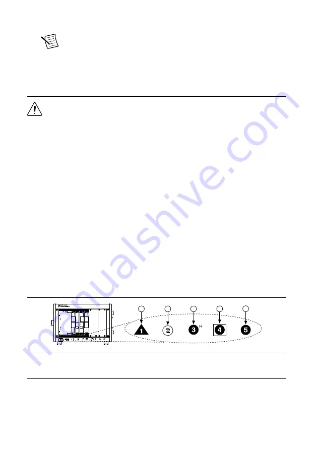
5. Identify a supported slot in the chassis. The following figure shows the symbols that

indicate the slot types.

Figure 2.

 Chassis Compatibility Symbols

NI PXIe-1062Q

1

2

3

4

5

1. PXI Express System Controller Slot
2. PXI Peripheral Slot
3. PXI Express Hybrid Peripheral Slot

4. PXI Express System Timing Slot
5. PXI Express Peripheral Slot

PXIe-5665 modules can be placed in PXI Express peripheral slots, PXI Express hybrid

peripheral slots, or PXI Express system timing slots.

6. Touch any metal part of the chassis to discharge static electricity.

PXIe-5665 Getting Started Guide

  | 

© National Instruments

  | 

7

Summary of Contents for PXIe-5665

Page 1: ...PXIe 5665...

Page 2: ...therwise specified the instructions for the PXIe 5665 in this document refer to both the PXIe 5665 3 6 GHz VSA and the PXIe 5665 14 GHz VSA Caution The protection provided by this product may be impai...

Page 3: ...gradation install and use this product in strict accordance with the instructions in the product documentation Furthermore any changes or modifications to the product not expressly approved by Nationa...

Page 4: ...amage Caution Never touch the exposed pins of connectors Note Do not install a device if it appears damaged in any way 3 Unpack any other items and documentation from the kit Store the device in the a...

Page 5: ...ble x3 Part Number 763718 01 6 3 6 GHz Version Flexible 5 inch RF SMA to SMA Cable Part Number 190412B 05 14 GHz Version Flexible 7 inch RF SMA to SMA Cable Part Number 190412B 07 7 SMA Driver Bit Par...

Page 6: ...EF OUT 10 MHz connector on the PXIe 5653 front panel to the REF IN connector on the back of the PXI Express chassis NI RFSA versions 2 5 and later do not require this connection Preparing the Environm...

Page 7: ...rovides standard IVI based functionality needed for most vector signal analyzer applications Use NI RFSA to create custom measurements or applications that require I Q data Use NI RFSA along with the...

Page 8: ...the right of the PXIe 5603 or PXIe 5605 RF downconverter module 1 Ensure the AC power source is connected to the chassis before installing the module The AC power cord grounds the chassis and protects...

Page 9: ...hassis which can improve the signal quality and electromagnetic performance 11 Cover all empty slots using EMC filler panels or fill using slot blockers to maximize cooling air flow depending on your...

Page 10: ...V p p MAX REF OUT 10 MHz 0 5 V rms REF OUT 100 MHz 0 5 V rms ESD SENSITIVE ACCESS ACTIVE OUT IN LO3 LO2 LO1 ALL PORTS 50 NI PXIe 5603 Downconverter 20 Hz 3 6 GHz RF IN 0 V DC DC COUPLED 25 V DC MAX AC...

Page 11: ...nel 2 Using the flexible SMA to SMA cable connect the REF OUT 100 MHz connector on the PXIe 5653 front panel to the CLK IN connector on the PXIe 5622 front panel 3 Using the short semi rigid SMA to SM...

Page 12: ...03 or PXIe 5605 The PXIe 5603 or PXIe 5605 is a precision RF instrument that is sensitive to ESD and transients Ensure you are making proper direct connections to the PXIe 5603 or PXIe 5605 to avoid d...

Page 13: ...e 5605 Downconverter 20 Hz 14 GHz IF OUT 22 dBm MAX 0 V DC LO1 LO2 LO3 ESD SENSITIVE LO3 LO2 LO1 ALL PORTS 50 15 dBm MAX 25 V DC MAX 15 dBm MAX 0 V DC ACCESS ACTIVE RF IN 0 V DC 20 dBm MAX 10 MHz 10 d...

Page 14: ...ector is between 2 VDC and 2 VDC With the DC block removed the maximum allowed voltage is 0 VDC Caution To reinstall the DC block on the PXIe 5603 or PXIe 5605 RF IN connector use a torque wrench set...

Page 15: ...GHz source In multichannel systems LO2 OUT exports the signal received at LO2 IN to other PXIe 5603 or PXIe 5605 modules LO2 OUT is disabled by default LO2 OUT is an SMA connector with an impedance o...

Page 16: ...eady to be programmed by NI RFSA ACTIVE Indicates the module state OFF The module is in a quiescent state AMBER The module is waiting for the Advance Trigger from the configuration list GREEN The modu...

Page 17: ...ront panel contains four connectors and two LEDs Figure 7 PXIe 5622 IF Digitizer Module Front Panel ACCESS ACTIVE CLK IN CLK OUT PFI 1 ESD SENSITIVE TTL 6 3 Vp p MAX 2 Vp p NOM 20 dBm MAX 50 50 50 16...

Page 18: ...5605 RF downconverter for digitization and measurement CLK IN Connects to the 100 MHz REF OUT connector on the PXIe 5653 LO source module This connector is the input terminal for the Reference Clock o...

Page 19: ...dy to be programmed by NI RFSA ACTIVE Indicates the module state OFF The module is in a quiescent state AMBER The module is waiting for the Advance Trigger from the configuration list GREEN The module...

Page 20: ...Ds Figure 8 PXIe 5653 Synthesizer LO Source Module Front Panel ESD SENSITIVE ACCESS ACTIVE LO3 800 MHz LO2 4 GHz LO1 3 2 GHz 8 3 GHz OUT ALL PORTS 50 NI PXIe 5653 Synthesizer REF IN 10 MHz 5 V p p MAX...

Page 21: ...5653 Synthesizer LO Source Front Panel Connectors Connector Use REF IN Routes a frequency reference signal to the RF synthesizer LO source This connector accepts a 10 MHz frequency signal with a maxi...

Page 22: ...a power rail AMBER The module is being accessed Accessed means that the device setup registers are being written to in order to control the device GREEN The module is ready to be programmed by NI RFSA...

Page 23: ...alled modules If the module is still not listed power off the system ensure the module is correctly installed and restart 4 Record the identifier MAX assigns to the hardware Use this identifier when p...

Page 24: ...following situations After first installing and interconnecting your PXIe 5665 system When there is a physical change to any of the system components such as replacement of modules When there is a cha...

Page 25: ...e directory and import library files located in one of the following directories Windows 10 32 bit 8 1 32 bit 7 32 bit NIDir Shared ExternalCompilerSupport C include Windows 10 64 bit 8 1 64 bit 7 64...

Page 26: ...les x86 IVI Foundation IVI Microsoft Visual C C Use the header files located in the IVIROOTDIR32 Include directory and import library files located in the IVIROOTDIR32 Lib directory where IVIROOTDIR32...

Page 27: ...g an Application with Microsoft Visual C and C topic of the NI RF Vector Signal Analyzers Help if you prefer to manually add all required include and library files to the project Programming Examples...

Page 28: ...mples Troubleshooting If an issue persists after you complete a troubleshooting procedure contact NI technical support or visit ni com support Installation Why Is the ACCESS LED Off When the Chassis I...

Page 29: ...nfirm that a PXIe 5665 entry appears Note If you are using a PC with a device for PXI remote control system under System Devices also confirm that no error conditions appear for the PCI to PCI Bridge...

Page 30: ...upport or visit ni com support What Should I Do if the NI RFSA Soft Front Panel Does Not Launch 1 Verify the front panel interconnections for your RF vector signal analyzer 2 Verify the MAX device ass...

Page 31: ...Learn LabVIEW Basics Getting Started with LabWindows CVI Support ni com support This item is also installed with the driver software EXPLORE LEARN CREATE DISCOVER RF Solutions ni com rf Services ni c...

Page 32: ...in the DoC for your product by visiting ni com certification If your product supports calibration you can obtain the calibration certificate for your product at ni com calibration NI corporate headqua...

Page 33: ...s EULAs and third party legal notices in the readme file for your NI product Refer to the Export Compliance Information at ni com legal export compliance for the NI global trade compliance policy and...

Reviews: