background image

Installing the PXIe-5413

Caution


To prevent damage to the PXIe-5413 caused by ESD or contamination,

handle the module using the edges or the metal bracket.

Caution


Clean the hardware with a soft, nonmetallic brush. Make sure that the

hardware is completely dry and free from contaminants before returning it to
service.

The PXIe-5413 is a single-slot module with one backplane connector. The module may be
installed into any PXI Express-compatible slot.
1.

Ensure the AC power source is connected to the chassis before installing the PXIe-5413.

The AC power cord grounds the chassis and protects it from electrical damage while you
install the PXIe-5413.

2.

Power off the chassis.

3.

Inspect the slot pins on the chassis backplane for any bends or damage prior to
installation. Do not install a module if the backplane is damaged.

4.

Position the chassis so that inlet and outlet vents are not obstructed.

For more information about optimal chassis positioning, refer to the chassis
documentation.

5.

Remove the black plastic covers from all the captive screws on the module front panel.

6.

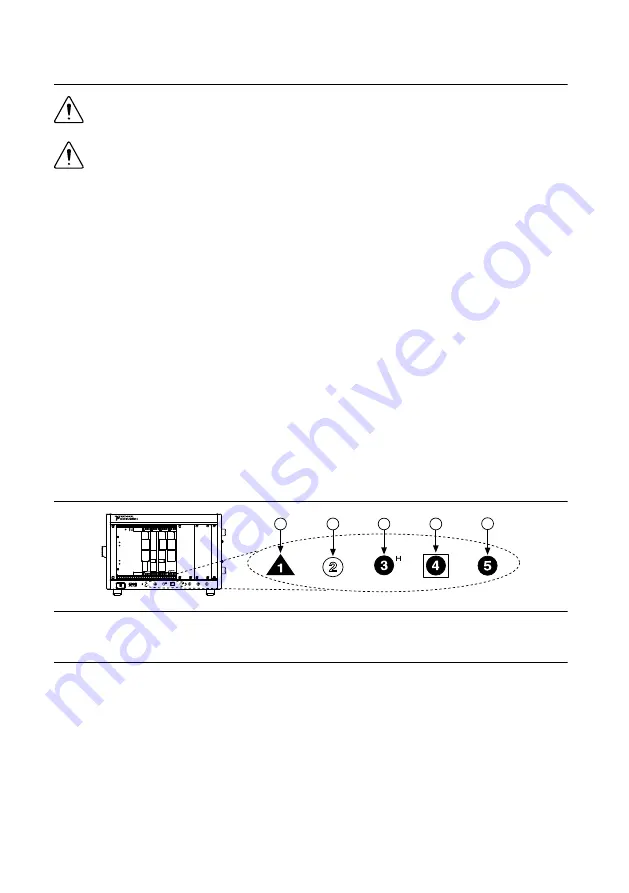
Identify a supported slot in the chassis. The following figure shows the symbols that
indicate the slot types.

Figure 2. Chassis Compatibility Symbols

NI PXIe-1062Q

1

2

3

4

5

1. PXI Express System Controller Slot
2. PXI Peripheral Slot
3. PXI Express Hybrid Peripheral Slot

4. PXI Express System Timing Slot
5. PXI Express Peripheral Slot

PXIe-5413 modules can be placed in PXI Express peripheral slots, PXI Express hybrid
peripheral slots, or PXI Express system timing slots.

7.

Touch any metal part of the chassis to discharge static electricity.

8.

Ensure that the ejector handle is in the downward (unlatched) position.

9.

Place the module edges into the module guides at the top and bottom of the chassis. Slide
the module into the slot until it is fully inserted.

PXIe-5413 Getting Started Guide

  | 

© National Instruments

  | 

5

Summary of Contents for PXIe-5413

Page 1: ...Electromagnetic Compatibility Guidelines 2 Verifying the System Requirements 2 Unpacking the Kit 2 Other Equipment 3 Preparing the Environment 4 Installing the Software 4 Installing the PXIe 5413 5 PX...

Page 2: ...product in strict accordance with the instructions in the product documentation Furthermore any changes or modifications to the product not expressly approved by National Instruments could void your a...

Page 3: ...xposed pins of connectors Note Do not install a module if it appears damaged in any way 3 Unpack any other items and documentation from the kit Store the module in the antistatic package when the modu...

Page 4: ...Operating relative humidity range 10 to 90 noncondensing Tested in accordance with IEC 60068 2 56 Indoor use only Related Information Refer to the PXIe 5413 Specifications at ni com for complete spec...

Page 5: ...s so that inlet and outlet vents are not obstructed For more information about optimal chassis positioning refer to the chassis documentation 5 Remove the black plastic covers from all the captive scr...

Page 6: ...ectrically connects the front panel to the chassis which can improve the signal quality and electromagnetic performance 12 Cover all empty slots using EMC filler panels or fill using slot blockers to...

Page 7: ...alog output terminal 2 CH 1 3 PFI 0 Input Output Imports digital trigger signals and exports digital event signals Imported digital trigger signals can start or step through waveform generation and ex...

Page 8: ...eset does not show an error The PXIe 5413 has powered down because the internal temperature exceeded the maximum limit The over temperature condition must be corrected and the hardware reset To reset...

Page 9: ...ce for signals 5 NC No connection 6 GND Ground reference for signals 7 GND Ground reference for signals 8 AUX 0 PFI 0 Bidirectional PFI line 9 AUX 0 PFI 1 Bidirectional PFI line 10 GND Ground referenc...

Page 10: ...igital signals to the AUX 0 connector on the PXIe 5413 front panel Refer to the following figure and table for information about the SCB 19 signals when connected to the AUX 0 front panel connector 1...

Page 11: ...appear under the name of their associated chassis 3 Expand your Chassis tree item MAX lists all modules installed in the chassis Your default names may vary Note If you do not see your module listed p...

Page 12: ...ule that is in the same chassis as the PXIe 5413 is installed uninstalled or moved When the PXIe 5413 is in an environment where the ambient temperature varies or the PXIe 5413 temperature has drifted...

Page 13: ...oad dialog box choose a waveform from the Waveform list 4 Click OK 5 Click Run to start waveform generation To optimize the waveform select Edit Device Configuration and adjust the settings NI FGEN In...

Page 14: ...D fails to light after you power on the chassis a problem may exist with the chassis power rails a hardware module or the LED Caution Apply external signals only while the PXIe 5413 is powered on Appl...

Page 15: ...Device Manager a Under an NI entry confirm that a PXIe 5413 entry appears Note If you are using a PC with a device for PXI remote control system under System Devices also confirm that no error conditi...

Page 16: ...16 Bit AWG NI PXI 5413 PXIe 5413 Firmware Licensing Software is licensed pursuant to the software license agreements provided with the software or in the absence of such license agreements the Nationa...

Page 17: ...fication If your product supports calibration you can obtain the calibration certificate for your product at ni com calibration NI corporate headquarters is located at 11500 North Mopac Expressway Aus...

Page 18: ...ents EULAs and third party legal notices in the readme file for your NI product Refer to the Export Compliance Information at ni com legal export compliance for the NI global trade compliance policy a...

Reviews: