background image


Lucid Series RF Analog 

Signal Generator 

Benchtop Model 

User Manual  

Rev. 1.4 


Summary of Contents for Lucid Series

Page 1: ...Lucid Series RF Analog Signal Generator Benchtop Model User Manual Rev 1 4...

Page 2: ...m any cause whatsoever arising out of or in any way connected with the manufacture sale handling repair maintenance replacement or use of said products Representations and warranties made by any perso...

Page 3: ...13 2 2 Front Panel Controls 13 2 3 Front Panel Connectors 15 2 4 Rear Panel Connectors 16 3 Benchtop GUI 18 3 1 CW Tab 18 3 2 Modulation Tab 19 3 2 1 AM Amplitude Modulation 19 3 2 2 FM Frequency Modu...

Page 4: ...Phase Modulation 21 Figure 3 5 Pulse Definition 21 Figure 3 6 Pattern Sequence 22 Figure 3 7 Frequency Sweep 24 Figure 3 8 Power Sweep 25 Figure 3 9 List 26 Figure 3 10 Run Mode 27 Figure 3 11 System...

Page 5: ...id Programming Manual Jakob Apelblat 1 2 10 Jan 2021 Supporting Lucid PC application version 1 2 900 GUI version 1 15 or higher and TE Update Tool version 1 0 500 3 Benchtop GUI page 18 Reference fiel...

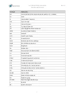
Page 6: ...nnector BW Bandwidth CW Carrier Wave DAC Digital to Analog Converter dBc dB carrier The power ratio of a signal to a carrier signal expressed in decibels dBm Decibel Milliwatts E g 0 dBm equals 1 0 mW...

Page 7: ...ystal Display LO Local Oscillator MAC Media Access Control address MDR Mini D Ribbon connector MHz Megahertz ms Milliseconds NCO Numerically Controlled Oscillator ns Nanoseconds PC Personal Computer P...

Page 8: ...io SMA Subminiature version A connector SMP Subminiature Push on connector SPI Serial Peripheral Interface SRAM Static Random Access Memory TFT Thin Film Transistor T M Test and Measurement TPS Test P...

Page 9: ...log Signal Generator LS3084B 3GHz Four Channel RF Analog Signal Generator LS6081B 6GHz Single Channel RF Analog Signal Generator LS6082B 6GHz Dual Channel RF Analog Signal Generator LS6084B 6GHz Four...

Page 10: ...s and describes the set of SCPI compatible Standard Commands for Programmable Instruments remote commands used to operate the Lucid devices The programs and the user manuals can be downloaded from the...

Page 11: ...cord To avoid electrical shock the grounding conductor must be connected to the ground Before connecting to the power input or output ensure that the product is properly grounded Do not operate this p...

Page 12: ...lable purchase replacement materials 2 Be sure the carton is well sealed with strong tape or metal straps 3 Mark the carton with the model and serial number If it is to be shipped show sending and ret...

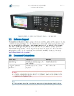
Page 13: ...today s most demanding requirements that is needed from the R D benches to the production lines 2 1 Unpacking Check that the packaging is undamaged If packaging is damaged notify the carrier immediate...

Page 14: ...button locks in the new variable and releases the buttons for other operations 2 When a parameter is modified Enter can be used to replace the x1 suffix key 3 When a discrete parameter is selected En...

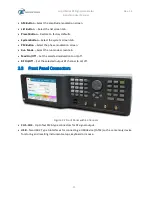
Page 15: ...ct the phase modulation screen Run Mode Select the run mode screen tab Mod On Off Set the selected modulation to on off RF On Off Set the selected output RF channel to on off 2 3 Front Panel Connector...

Page 16: ...channel for an input from an external amplitude modulation source TRIGGER IN Up to four BNC type connectors one for each channel for an input from an external trigger source LAN USB HOST RJ45 100BaseT...

Page 17: ...Lucid Series RF Signal Generator Benchtop User Manual Rev 1 4 17 Note The Lucid generator will automatically revert to external reference when a signal is detected at its input...

Page 18: ...of the screen displays a summary of the system status and is shown in all tabs Frequency The CW frequency Power The power amplitude of the output signal in dBm Phase The phase offset of the signal 0 3...

Page 19: ...ignal in dBm The default value is 5 00 dBm Phase Offset Sets the phase offset of the signal Phase offset range is between 0 degrees to 360 degrees The default value is 0 degrees 3 2 Modulation Tab The...

Page 20: ...he FM button on the front panel to show the screen Figure 3 3 FM Frequency Modulation Frequency Set the modulation Frequency Hz Deviation Set the frequency deviation of the carrier wave in Hz Source I...

Page 21: ...on the device front panel to start the modulation and then RF On Off button to output the signal 3 2 4 Pulse Definition Select on the device display the Modulation tab and then click the PULSE button...

Page 22: ...tton to show the pattern sequence parameters You can set a sequence of pulses according to the list of pulses where each step in the list defines a pulse Time On and Time Off time and the number of Lo...

Page 23: ...al Rev 1 4 23 6 Enter the duration of the pulse Time On the delay for next pulse Time Off and the number of repetitions Loops of this step 7 STEP Click the button to delete the last step 8 SEND Click...

Page 24: ...utton You can now define a signal that sweeps from one frequency to the next maintaining the same amplitude Figure 3 7 Frequency Sweep Following are the details of the frequency based Sweep menu Start...

Page 25: ...top Power stop power sets the stop sweep amplitude in dBm Dwell Time sets the sweep dwell time that is the duration of the entire sweep Step Size sets the size of each step in dBm in the sweep The val...

Page 26: ...vaScript Object Notation format You can select to store the data on the SD card or on the internal 4 DEL Click the button to delete selected step 5 STEP Click the button to add a new step Enter the fo...

Page 27: ...ected Source sets the source of the trigger The Enter key of the front panel will toggle the values Timer sets the rate for clocked triggers in ns s ms or s External an external source connected to th...

Page 28: ...nal Generator Benchtop User Manual Rev 1 4 28 Step for every trigger that is accepted the sweep or list is advanced by 1 step While the step is being generated any incoming trigger is ignored until th...

Page 29: ...f the generator Temp The temperature of the generator Options The options available in the generator MOD Modulation package AM FM PM PUS Pulse generator FS Fast switching LP Low Power 90 dBc EMU Emula...

Page 30: ...3 6 2 Store Select on the device display the System tab and then click the Store button to save the current settings of the entire system in a JSON JavaScript Object Notation format You can select to...

Page 31: ...ect Notation format You can select to restore the data from an SD card Figure 3 14 Recall Settings Load Click the button to load the system setting from selected file and storage device Erase Click th...

Page 32: ...button to return to the System dialog box 3 6 5 Update Select on the device display the System tab and then click the Update button to update the device software Refer to Lucid Control Panel User Manu...

Page 33: ...RF Signal Generator Benchtop User Manual Rev 1 4 33 Figure 3 16 System Update 6 Wait for the operation to complete 7 The device will reboot automatically BACK Click the button to return to the System...

Page 34: ...LS1292B LS1294B 9 kHz to 12 GHz Resolution 0 001 Hz Phase Offset 0 01 deg Switching Speed Standard 500 s FS Option 100 s Frequency Reference Temperature Stability 25 ppb max Aging 3 ppm max for 20 yea...

Page 35: ...Phase Noise and Harmonics Specification Phase Noise dBc Hz Measured 10 kHz Offset 1 GHz 138 typ 2 GHz 133 typ 3 GHz 130 typ 6 GHz 124 typ 12 GHz 118 typ Harmonics dBc Up to 100 MHz 30 dBc 100 MHz to 1...

Page 36: ...ble 90 Resolution 0 1 of depth Accuracy 1 kHz 4 of setting Modulation Rate DC to 100 kHz Phase Modulation Peak Deviation 360 deg Modulation Rate DC to 100 kHz Pulse Modulation PLS Option On off Ratio...

Page 37: ...Inputs Specification Inputs Modulation Connector Type BNC per channel Input Impedance 50 Maximum Input Voltage 1 V Input Damage Level 3 5 V Pulse Trigger Connector Type BNC per channel Input Impedanc...

Page 38: ...1294B 4 Reference Out Impedance 50 Connector Type 2 x BNC Frequency 10 MHz 100 MHz Shape Sine Power 3 to 7 dBm 4 7 General Table 4 7 General Specification General Voltage Range 90 VAC to 264 VAC Freq...

Page 39: ...425 mm Without Feet 315 X 88 x 425 mm Weight Without Package 6 kg Shipping Weight 6 5 kg Temperature Operating 0 C to 40 C Storage 40 C to 70 C Warm up time 15 minutes Humidity 85 RH non condensing Sa...

Reviews: